

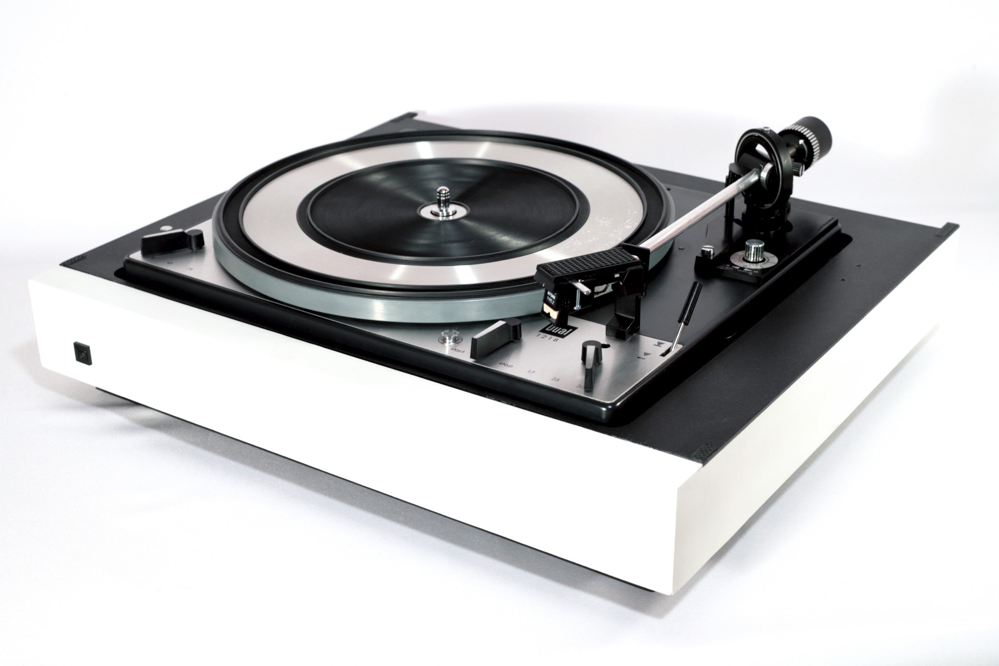
DUAL 1218 Turntable Restoration
Inspection – that’s always a first step of every maintenance or restoration project that I do. Even if it’s my own table like in this case. Why it’s so important you wonder ? Well, there is nothing more miserable then testing freshly rebuild turntable and realizing that you missed something that was not working in a first place. Or owner didn’t told you, because he forgot or wasn’t aware of himself. And now you have to disassemble everything all over again. Don’t ask me how I know this stuff.

Obviously first thing to do is plug it in mains and see what happens. Sometimes you let the magic smoke out and sometimes it just works. Either way, what an excitement ! This time though, it was disappointment. Pushing and turning all possible switches didn’t produce any reaction whatsoever. Nothing. Nada.
Next thing was a checklist. Here is what I usually do:
- Cosmetics
- Inside condition
- Mechanical functions
- Electrical
If it’s newer table, I might add drive electronics overview, but here we have an good old on/off switch only. Now let’s go through this list together.
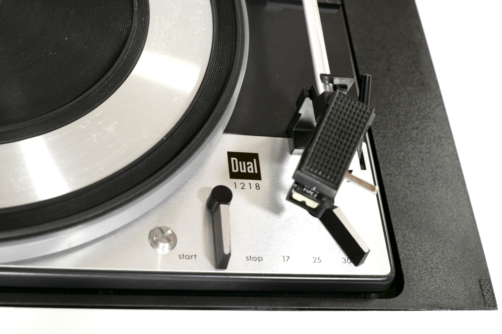
Cosmetics
Overall cosmetic condition was fair enough. I couldn’t see any obviously broken parts, scratched paint or other show stoppers. Although paint or plastic laminate on wooden body was in poor condition. It was discolored quite profoundly. I wonder was it ABS laminate with Bromide ? That thing famously turns from white to yellow over long exposure to UV light. You can see this happening with old PC’s and whatnot.


All the markings and lettering for controls was intact, which is always nice. You can’t do much really if they’re damaged or wear of from usage. These letters and logos were transferred using silk-screening in factory and there isn’t any quick or modern method to do a face-plate any other way. There was a thing, actually company, called Letraset which produced dry rub on transfers. If you are lucky, you can find those transfers for a well known turntable models. But even then, you must clear-coat whole face-plate, because they come of very easily. Stickers or dry transfers look terrible. Of course you can always go to your local printing house and order new silkscreen, but you will not like pricing. I promise you that.
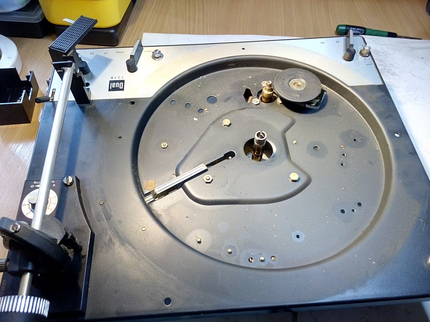
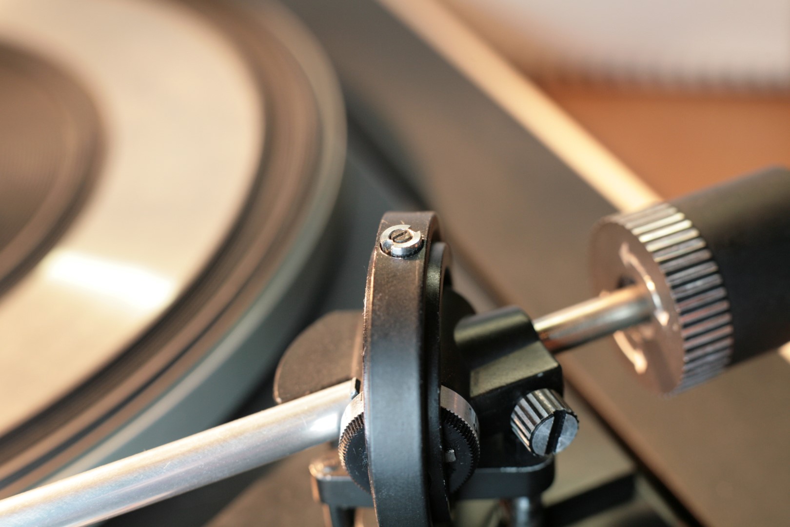
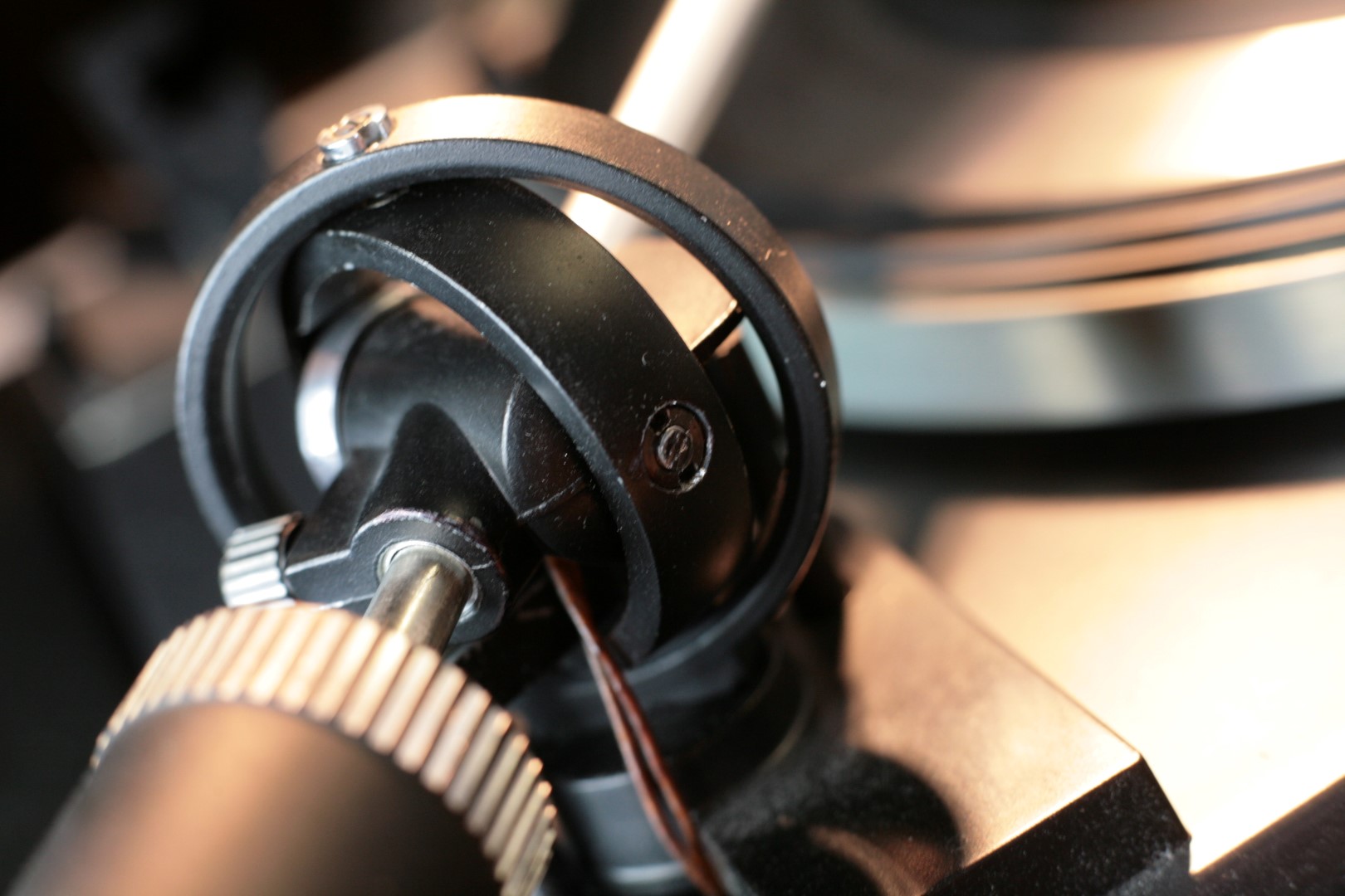
Dust and cobwebs – the usual suspects, were all over the place. Nothing astonishing after such a long storage. Tonearm gimbals were affected most of all. You can see all the gunk gathered near the lifting mechanism. This is a best example of why you should never oil your tonearm. All that dust was attracted by damping oil sipping through the lifting leg and it was stuck. I could really tell that tonearm vertical and horizontal movements were also somehow impaired by all this filth.
Inside Condition
Nothing out of ordinary could be seen at first glance. No broken, hanging or otherwise misplaced parts. And most importantly no marks of previous repairs! Don’t even get me started on this. There are few things worse in life then sorting someone else’s mess. And I will not name them. Let’s keep this content kids-friendly.


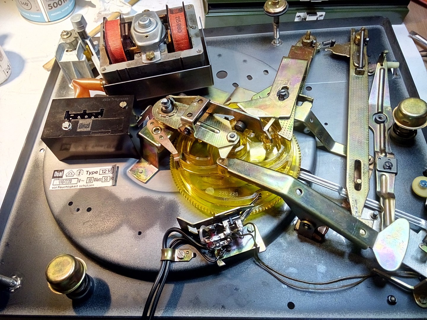
Just a couple remarks. Motor armature had some rust on it and all the lube on contact surfaces had dried and hardened. That rust doesn’t affect any functionality whatsoever, but it looks ugly for sure. Fortunately it’s an easy fix. Couple passes with sand paper and some oil should do the trick. All that hardened lube, on other hand, presents a real problem. It’s really impairing the movement of sliding parts and thus renders all the changer and start-stop functions unusable.
Electrical and Mechanical Functions
As you remember this table was not functioning at all. This is usually a good thing. Don’t laugh, really! It means that there is a chance for an easy repair. Motor is not spinning because of electrical discontinuity, or the switch is not actuated by the start-stop mechanism. Either way, I couldn’t assess any mechanical functions until it was working again.

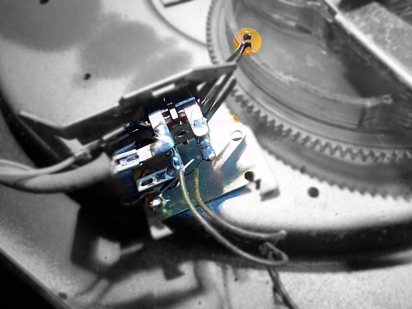
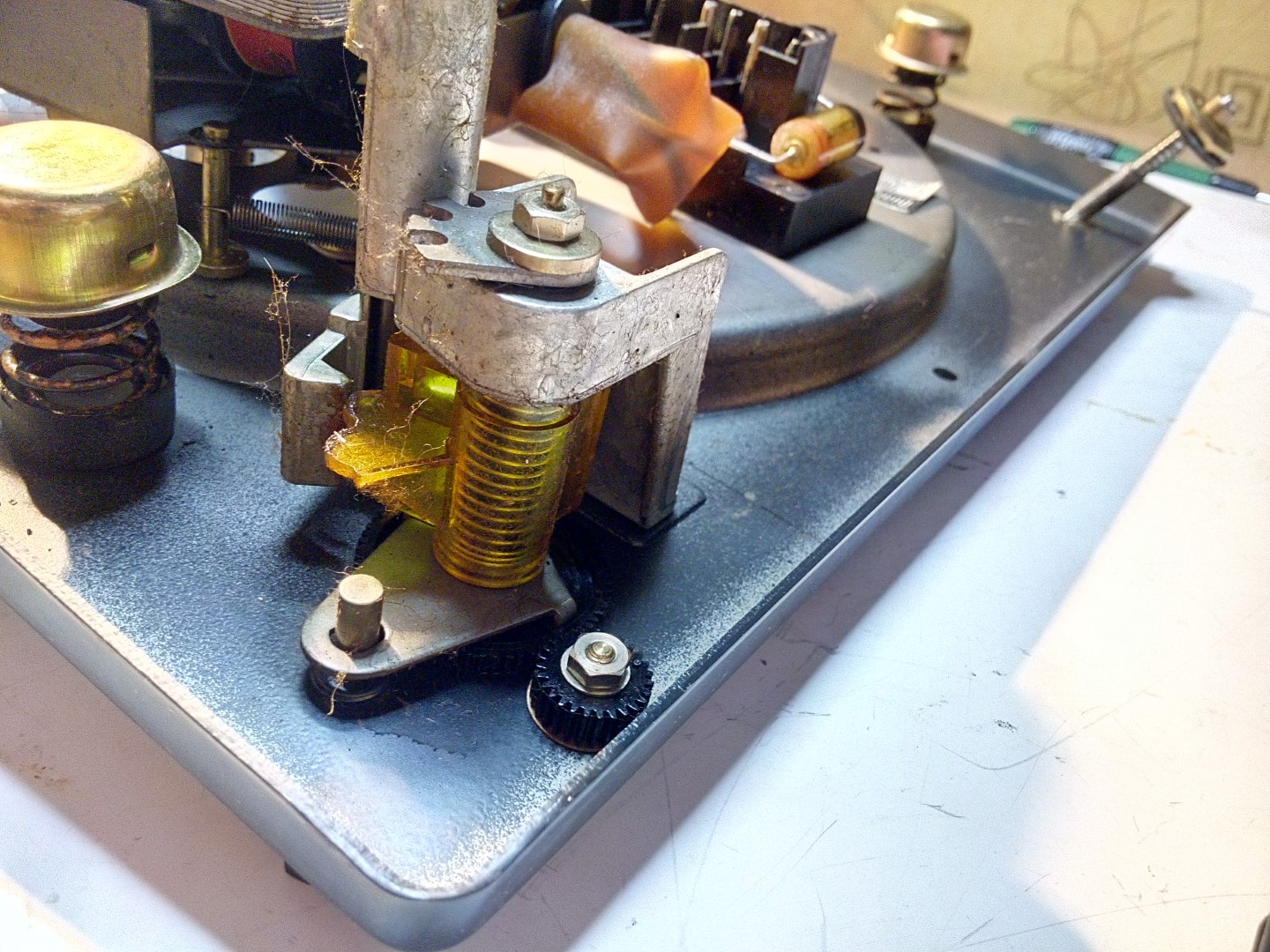
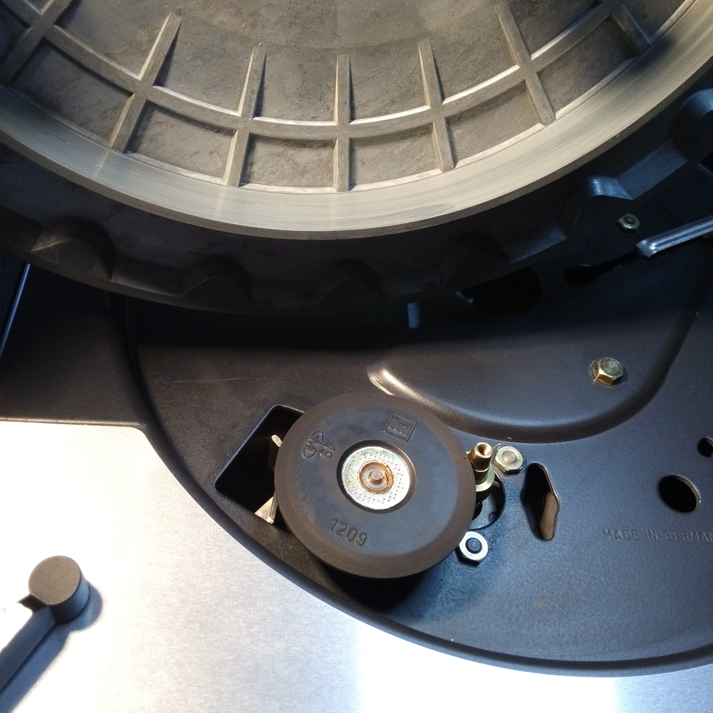
First thing to check was actual motor. I quickly soldered spare mains plug directly to motor terminals 3 and 4 and plugged it in the socket. It’s alive ! That was a good news. Next suspect was a switch. Activating it manually didn’t produce any results so it was time to clean and polish it with a very fine sandpaper. Upon further inspection I noticed a lot of oxidation everywhere around switch box. It could’ve been stored in a damp place it seems. Anyhow, after switch cleaning, table started for the very first time! Only to stop in a middle of tonearm lift cycle couple seconds later. It was evident that all this hardened grease was doing it’s job. And here goes WD40 to the rescue. I don’t use it anywhere near any turntable, but it’s perfect for temporary dissolving hardened grease. Good spray, and 10 minutes later, it was operating as it should. I had first full start-stop cycle, but then things went south. There was this sporadic behavior when table suddenly stopped or refused to start again. It was obvious that something else was amiss.
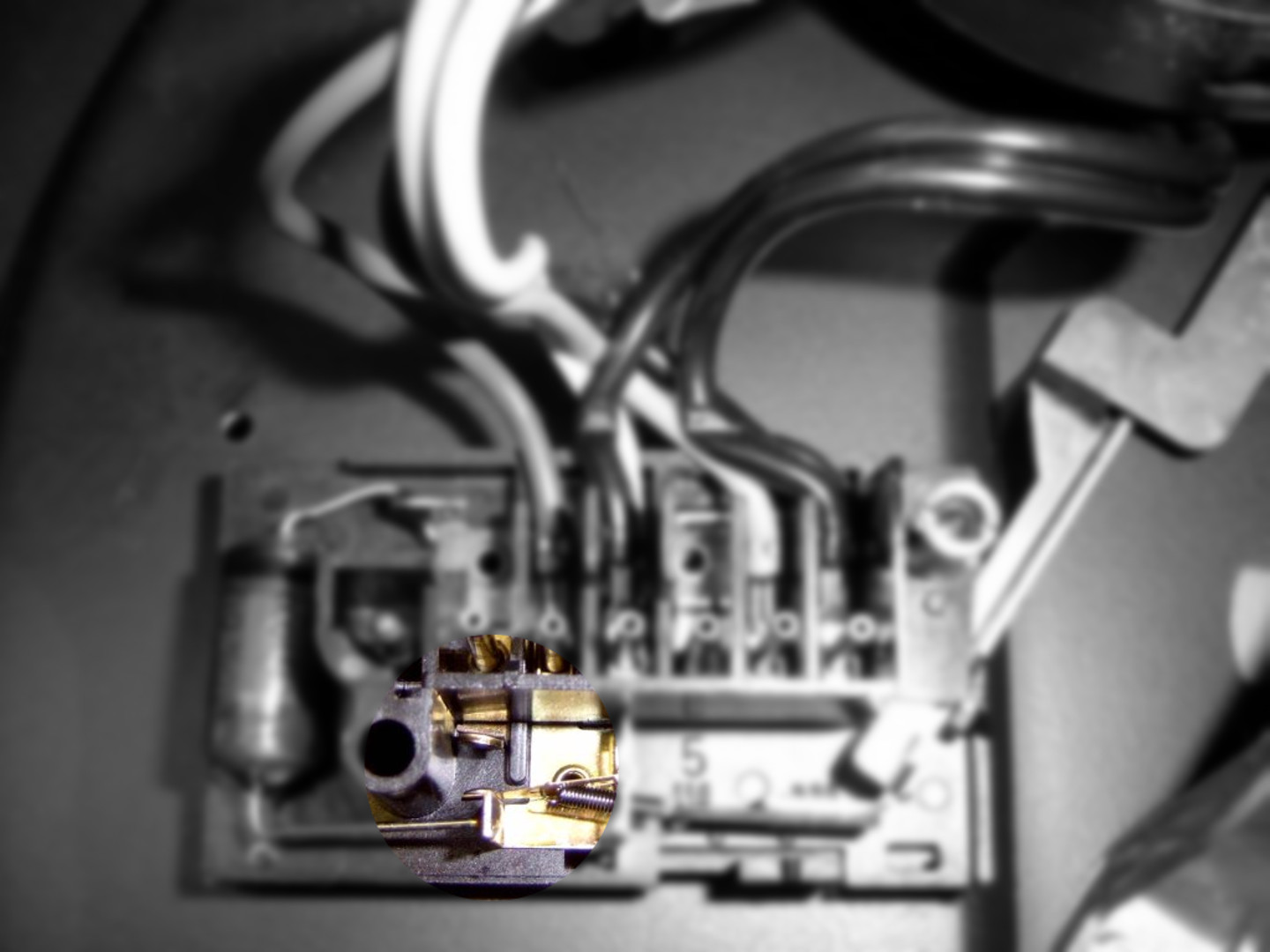
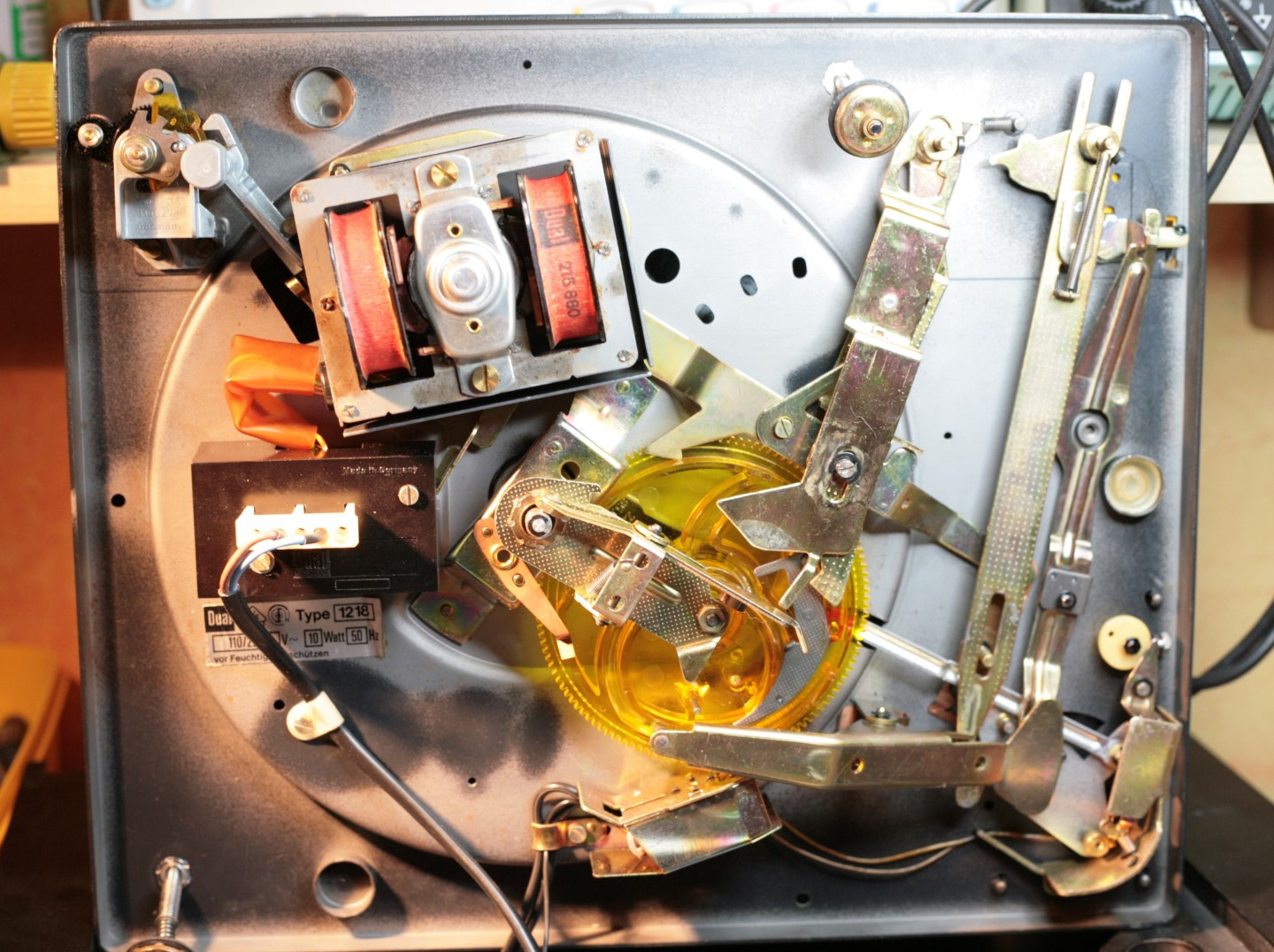
I had my eye on these connectors for motor supply. They were almost black from oxidation and their whole assembly looked quite suspicious. I don’t know why they chose those ring terminals for motor wires. They are kept in place only by a small surface of terminals outer sleeve. I got bored cleaning them and getting intermittent interruptions – so soldering it is. After that, it was starting and stopping like a clock. Could’ve been done at factory really, but well… It’s faster to put connectors in, I guess.
Further inspection revealed broken tonearm wires on junction board. Also muting switch contacts were oxidized. Again, an easy fix. Those old DIN wires goes to a trash bin.
It’s a Bath Time!
If I could give one advice before any disassembly, I would say take as much photos as you can. Believe me, it will make your life so much easier. This table is not very complicated, so one with even minimal technical skills and experience will be able to put it back again. But will it work ? That’s a whole different question. Here is were service manual comes in handy. It’s not always you have this luxury, but it always pays off finding, or buying one.


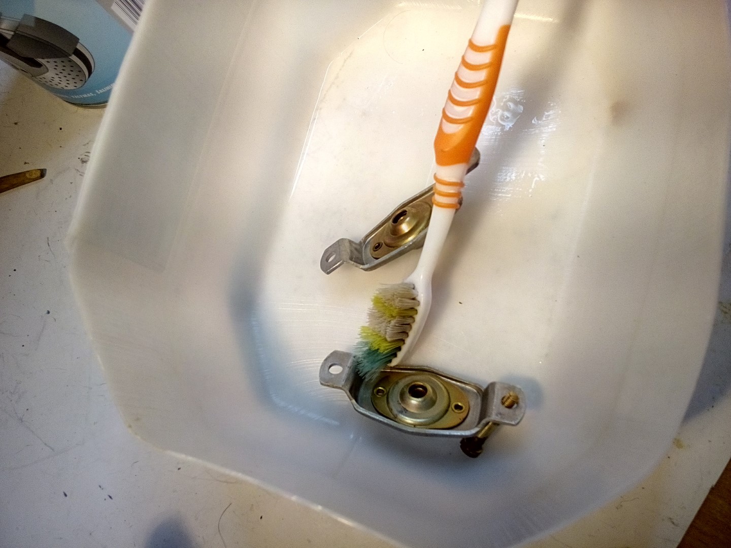
For a face-plate, platter and all visible parts, which has any paint or lettering on them, I like to use simple industrial soap. Make sure it has no additives, such as hand cream or abrasive particles and watch out for that silk-screen lettering! For all inside moving parts, that has some old grease on them, I use engine cleaner. Just put those parts in separate plastic container, spray it and leave it for 10 minutes. Remember to put on your gloves or wash your hands immediately, this stuff is quite aggressive. Now watch as all this gunk will easily wash off with simple brush and water.
Motor and Tonearm

Motor disassembly is quite straightforward. Watch out for that spacing washer on a rotor axle. Only serviceable parts are bearing hubs. Give them a good scrub with some miniature brush. For cleaning bearings I always use naphtha. It has many names depending on where you live – white spirit, coleman fuel, camp fuel, lighter fuel, paint thinner etc. Essentially it’s high petroleum distillate – jet grade fuel. It’s not as dry as acetone or other highly volatile substances, thus it leaves a micro oil film and prevents parts from rusting. If it’s especially bad case, or part has hard to reach surfaces, good spray of brake cleaner does it’s job wonderfully.

Now, with tonearm it’s whole different story, and I would strongly advise against it’s disassembly. Do it only if you really have no other option, for example when bearings are loose, or there is evidence of corrosion. Otherwise clean it externally and give a good spray of brake cleaner directly to bearing hubs. Using the straw that came with a spray can is a good idea.


The most significant reason for why you should avoid tampering with tonearm is those lock-nuts 42 and 57. There is no readily available spanner wrench small enough to fit them. Try using mini snap ring pliers and you will likely make a real mess. Stripping paint all over and damaging the threads is the usual outcome. I use special tool that I made just for these lock-nuts. Nothing fancy, just two pieces of 1mm micro screwdriver spaced 5mm apart with 3mm hole in a middle. Usually it fits other tonearms too, so a worthy time investment. And then there is never ending adjustment for vertical and letterer bearing play. There shouldn’t be any, but at the same time bearings can’t be tight. It’s more of a feel thing really and it comes with a practice.
Where Does This Thing Go ?
Assembly is my favorite part. Everything is shiny and looks new. You basically go through the same process as the person in factory, who build it originally. There is always this anticipation to finally see it finished and hopefully looking the same, as it was new.

I will not go in a full detail step-by-step assembly instructions here. There is an excellent service manual available, which has detailed exploded-view illustrations for that. I will just mention couple potential traps for young players to watch out for.
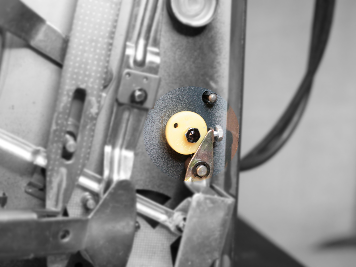

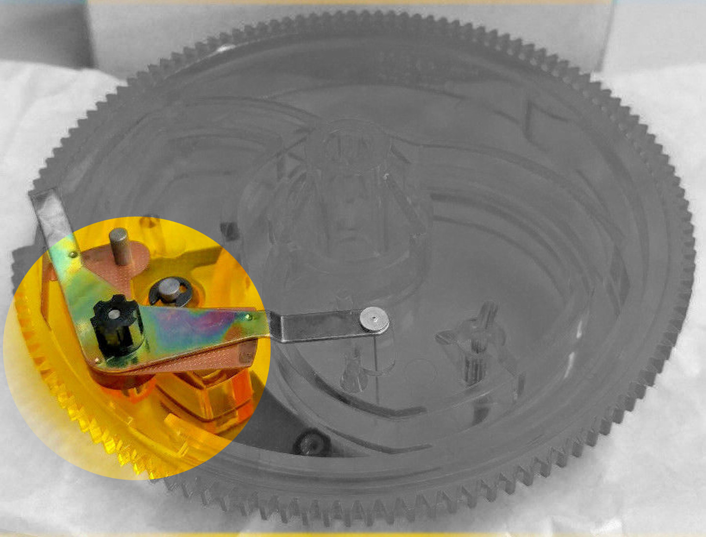
Don’t touch that set screw (203) on the skating lever (195). It’s preadjusted at the factory for conical (red scale) and elliptical (black scale) styli anti-skating pressure. You will need a special head-shell with a torsion meter to readjust it. Take your time to correctly position and tighten the plastic cam wheel (200). It should be fully pushing the skating lever when the adjustment knob is set for 0. It’s best to check this by making sure that the table is at level and the tonearm is fully balanced. Setting anti-skating to 0, should enable the tonearm to stay in one place without moving anywhere.
Before putting cam in, adjust stop nut (156) that is holding shut off lever (157) and friction plate (158) together. Parts 156 and 157 should remain stationary when cam is rotated in hand and effected by gravity. They should move only when you tap them very gently. Again, more of a feel thing.
Lubrication
Here is where service manual comes to the rescue. Many people underestimate the importance of proper lubricants usage. What they don’t understand is that some functions were designed to work only when certain lubricant is used. Tonearm lift is a best example. Ever tried putting simple oil on a lift bolt? Just don’t. Unless you want to see your tonearm jumping like a frog.


Service manual calls for specific lubricants, which are not available anymore. From what I was able to gather over the net, I made a list with modern replacements:
- Wacker silicone Oil 300 000 – any silicone oil with viscosity of 300 000 cSt. Try RC hobby shops for “shock absorber/differential oil”.
- Renotac No. 342 – any synthetic or mineral based oil with viscosity of ~100 sCt @ 40C. 10W40 motor oil will do just fine, although I go for a more tacky chain-saw oil.
- Viscostatic 10W30 – any synthetic or mineral based 10W30 automotive oil.
- Alvania No. 2 – any good quality lithium bearing grease.
- Isoflex PDP 40 – any synthetic or mineral based oil with good aging properties and viscosity of 10-20 sCt @ 40C0. I use Singer oil for sawing machines. It stays on surfaces for ages. Lubricants of same viscosity for clocks or camera shutters could be even better option.
I wouldn’t go crazy about exact substitutes. Using just silicone oil, grease, and any 10W40 engine oil for everything else, would do just fine, if it’s a one of project.
Head-shell Modification
Remember how I started this article with importance of meticulous inspection ? Yeah… So, it was time to mount a head-shell and I saw this:

That’s a broken adjustment shaft of TK 15 head-shell adapter for you. Usual sight I guess. And you know why I haven’t noticed this ? Because I don’t really care. If there is one part seriously lacking in this turntable – this must be it. I understand that this cheap, lousy and unreliable piece of plastic was a necessary evil from engineering point of view. You have to adjust VTA when stacking those records one upon another in multi record mode. And you have to do it for the budget. But I was not going to use any changer functions and for me that was massively unjustified compromise.
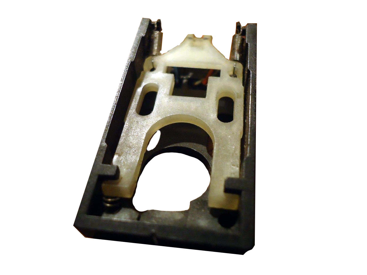
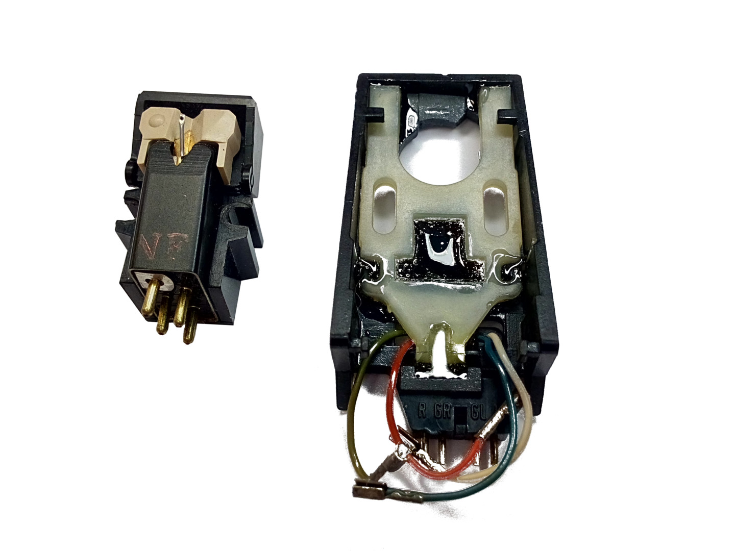
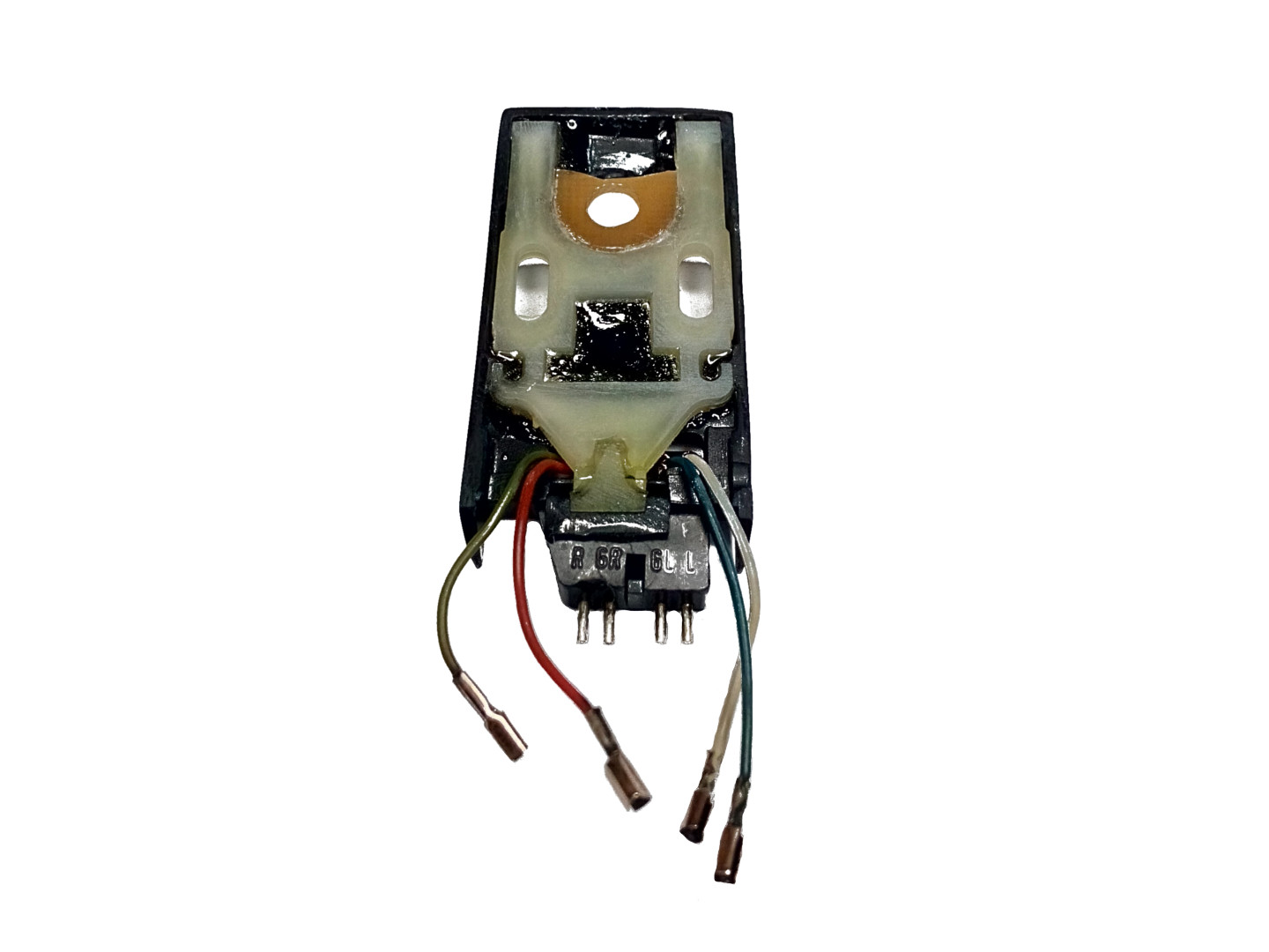
Just look at that lousy internal construction. Cartridge is mounted on this intermittent sliding plate, all flapping in a breeze. I won’t even start implying any resonance issues here, it’s ridiculous. People in tonearms R&D are going to great lengths nowadays with Solid Works and frequency analysis simulations and there is this thing…
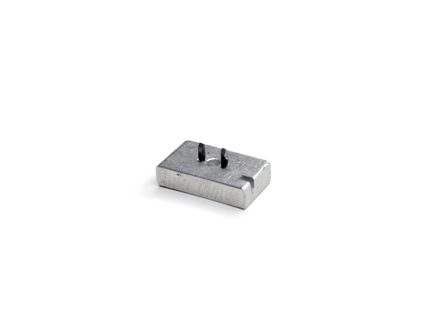
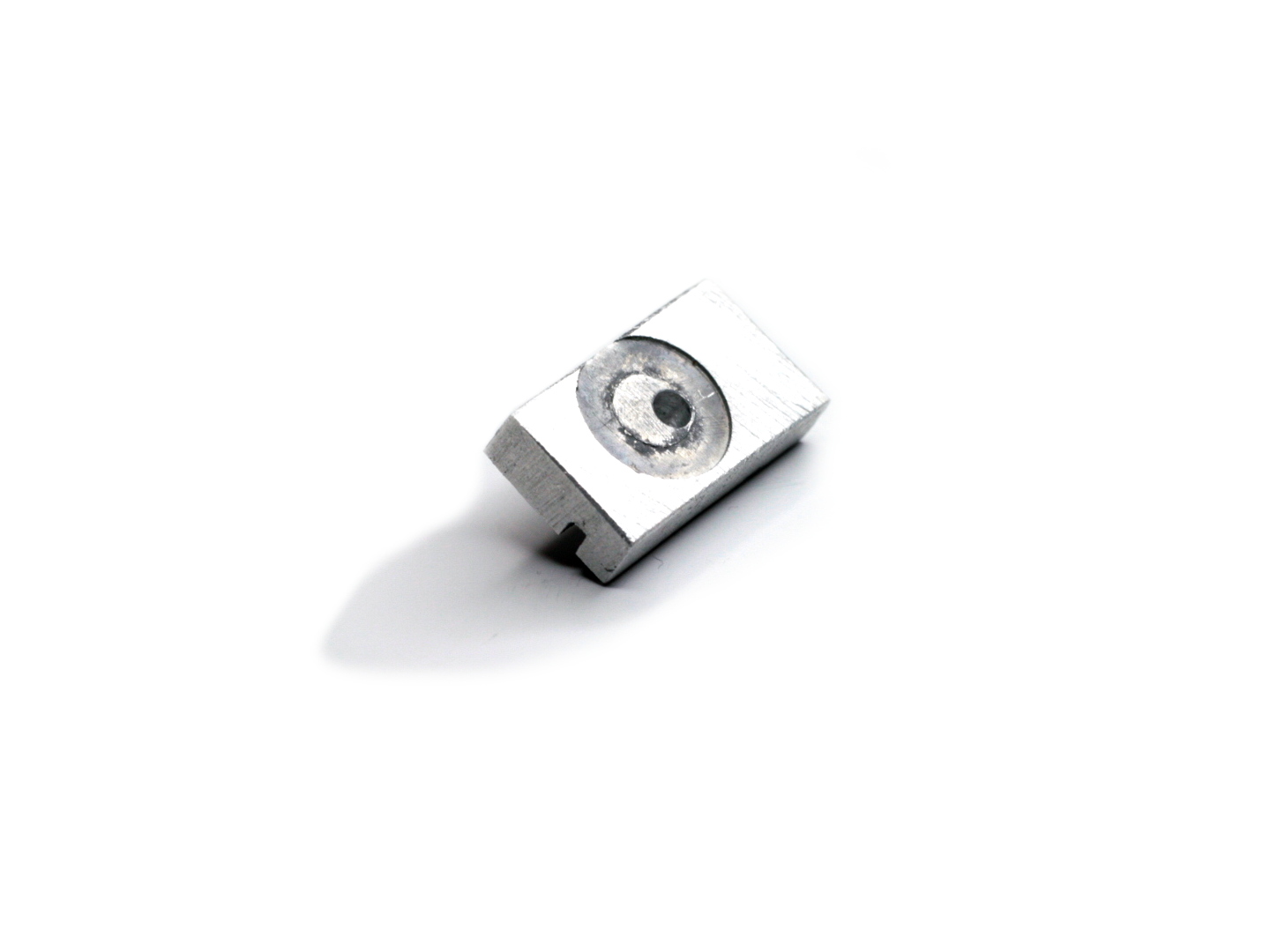
After potting that moving plate in epoxy, I test fitted this contemporary work of art, and still wasn’t satisfied. There was still plenty of movement left. Actually, there is a non adjustable adapter version TK 14(24) from Dual, and you can still buy them, but they have a same problem! Even when locked in place, there still is a considerable axial movement left, which renders any cartridge alignment useless. To solve this problem, I made an additional insert. Now, when locked in place, adapter is centered on a handle axle and sits there like a rock. Just the way it should.
Now That’s a New Angle !
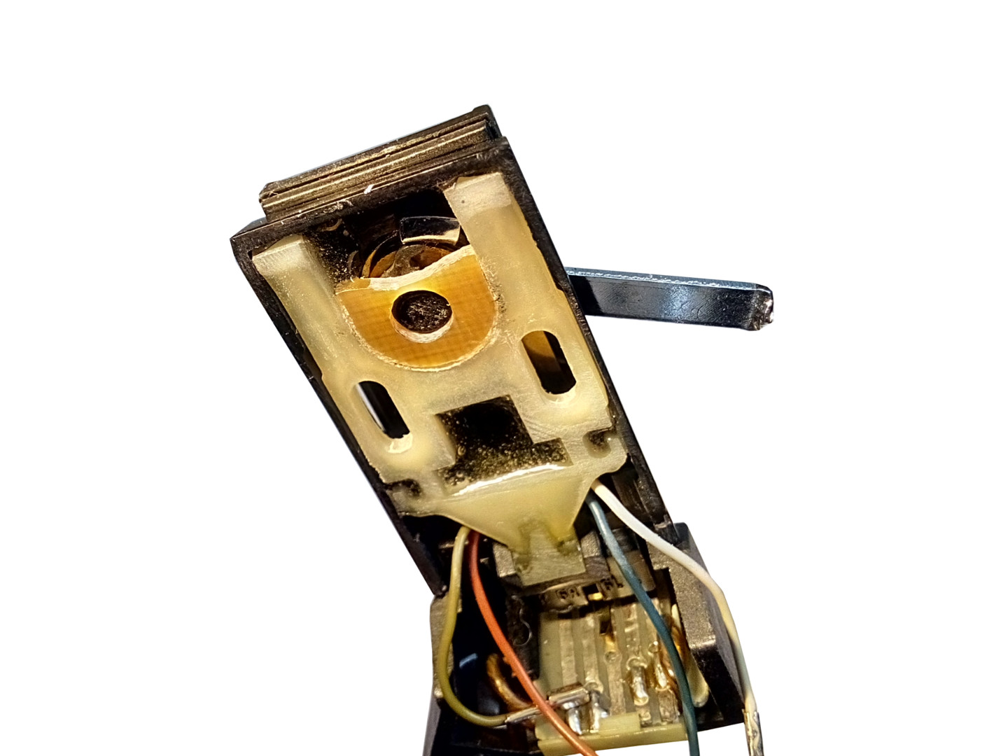
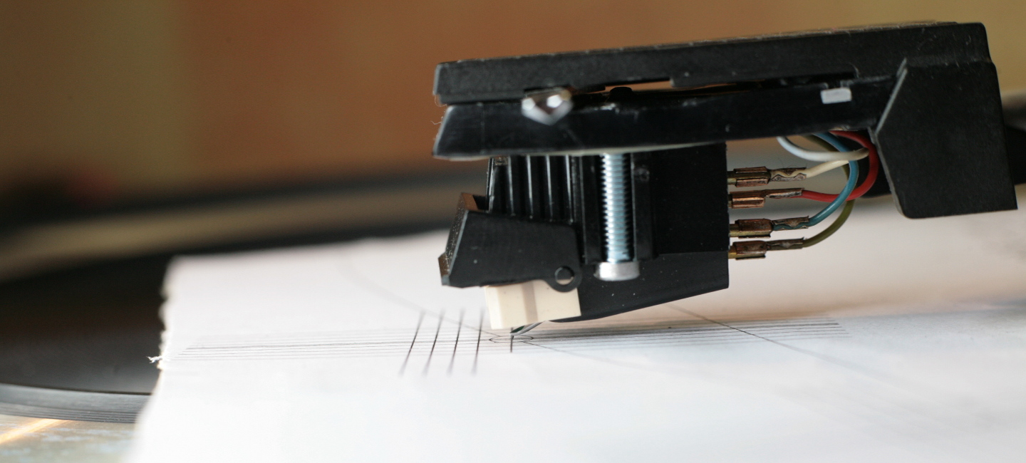
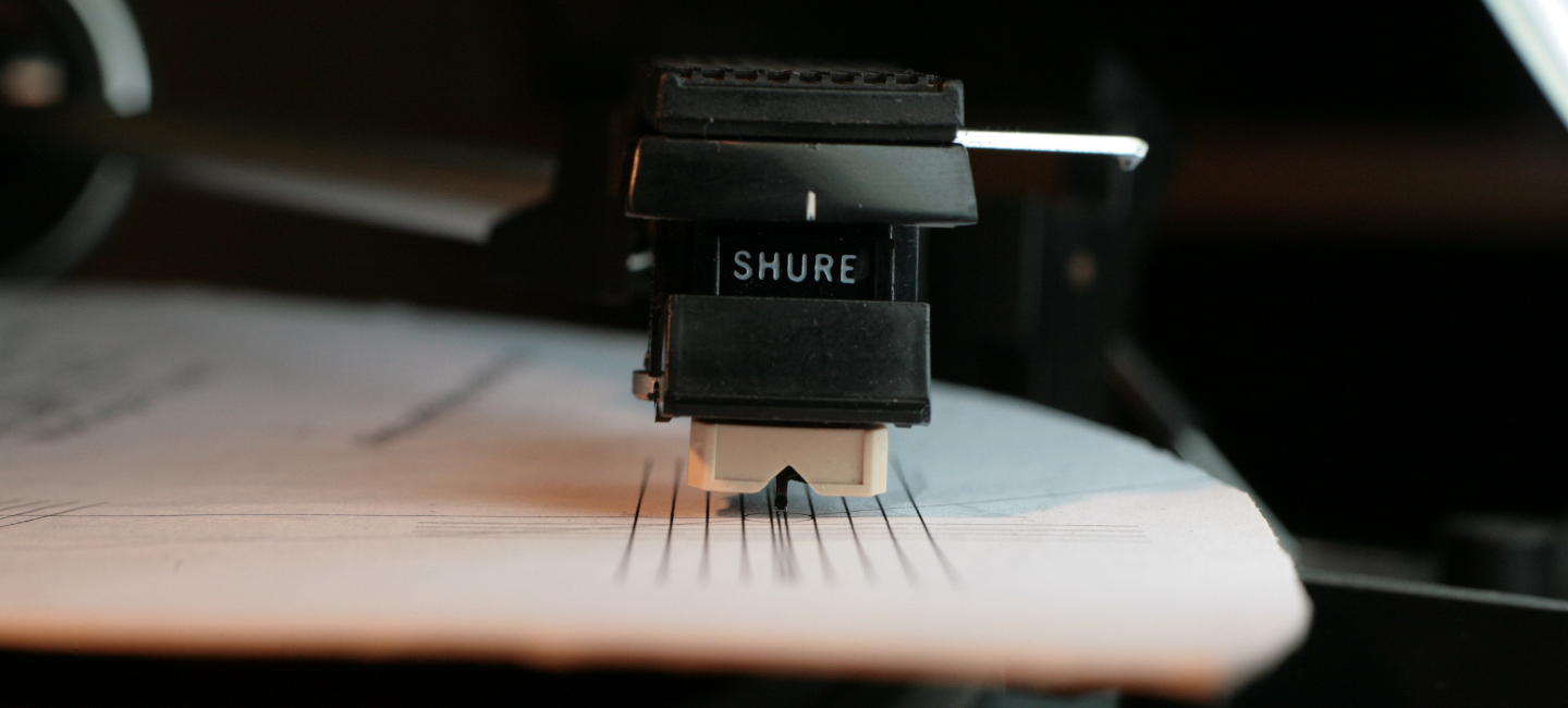
Ever wondered what happens over 30 years to a rubber suspension of cantilever? Wonder no more ! Here it is.


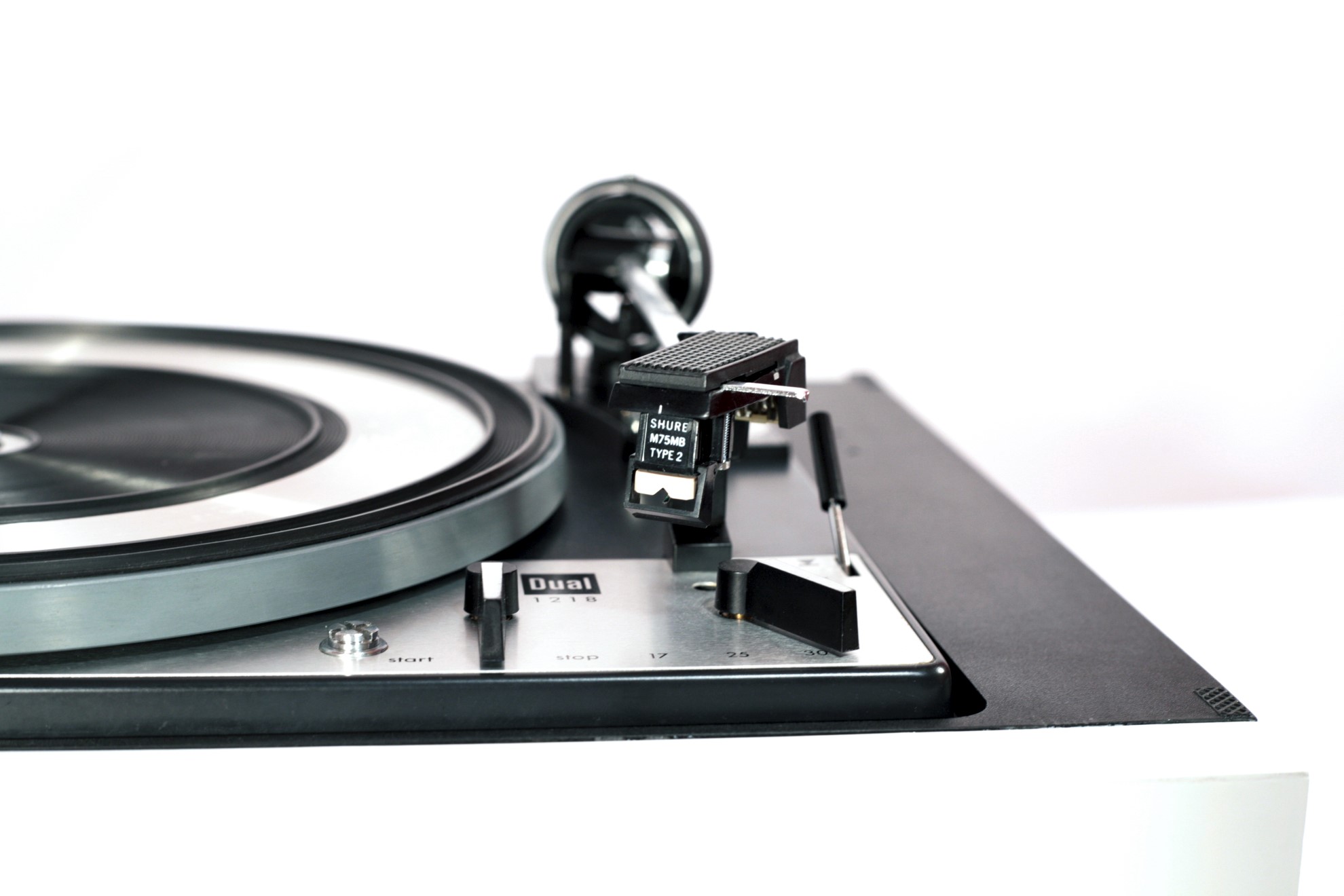
Now how about that VTA ? Even with those massive shims, it’s still not entirely where it’s suppose to be. Photos were made during playback of a record with 2g of tracking force. That’s more then the 1.5g max recommended for M75G II. In fact old stylus was not worn and it sounded ok I guess, but that suspension was gone. Luckily, you can still get N75G2 stylus replacements for a sensible price, so I went and ordered one. Seller assured me, that it will be a reasonably fresh direct replacement.
This should serve as a warning for all those lovers of “original” cartridges.
Cartridge Alignment
It’s a broad topic, certainly worthy of it’s own article. For the time being, this short guide will get you going in no time. First let’s measure the pivot-to-spindle distance. This will be a fundamental dimension that we will base all our efforts on, so care must be taken to make a precise one. Never blindly trust the internet for this kind of info, always check and measure yourself.
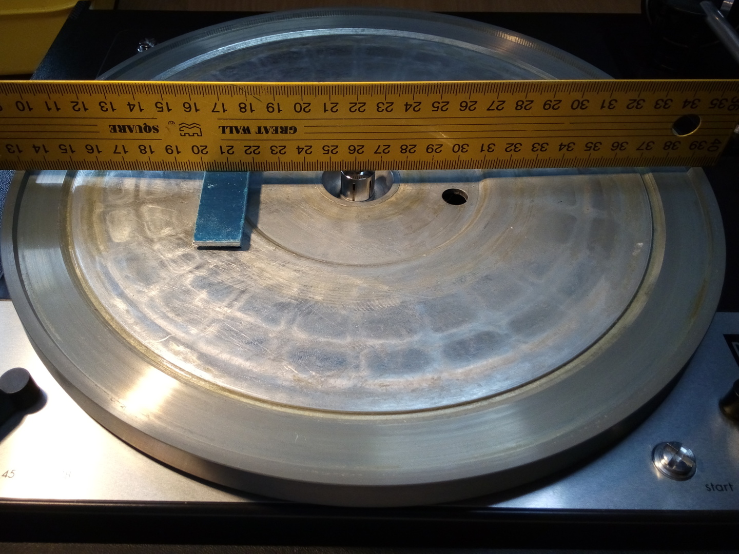


Above pictures are more or less self explanatory. Platter surface is concave, so we have to use some metal strips, to make it level and get a good square angle. Distance, from spindle surface to a center of bearing, measures exactly 188.5 mm. Spindle pin is 7mm, so we must subtract 1/2 of it to get a center to center length. That gives us exactly 185 mm. Now it’s time to generate a protractor. I use this wonderful tool from Conrad Hoffman. There are other template generators, but they all do the same thing. Here is a resulting protractor with Löfgren A optimization. Care must be taken when matching printing dimensions and cutting center hole. I always glue it to thick cardboard and use small office knife for centering pin hole. Now the fun part begins.

After making stylus follow the arc on protractor, and thus setting tonearm effective length, it’s time to go for an offset angle. Trying to align cantilever to the grid as best as possible, takes some time and patience. Usually it means starting from something like this:

And finishing with something like that:


Now, check again that stylus is still tracking the arc, and you’re all set. I always align cantilever and not the cartridge body. Just watch out for that deflection when setting down the stylus. Make sure there is no axial force bending it sideways. It’s time to finish by setting correct tracking force. Manual says from 0.75 to 1.5g for M75G II is what it should be.

Close enough.
Final Assembly
After giving that awful yellow body laminate a fresh white-mat repaint, it was time for a final assembly. Just two things was still bugging me. That rubber mat was glued originally and it doesn’t sit nicely just like that. So glued it must be.

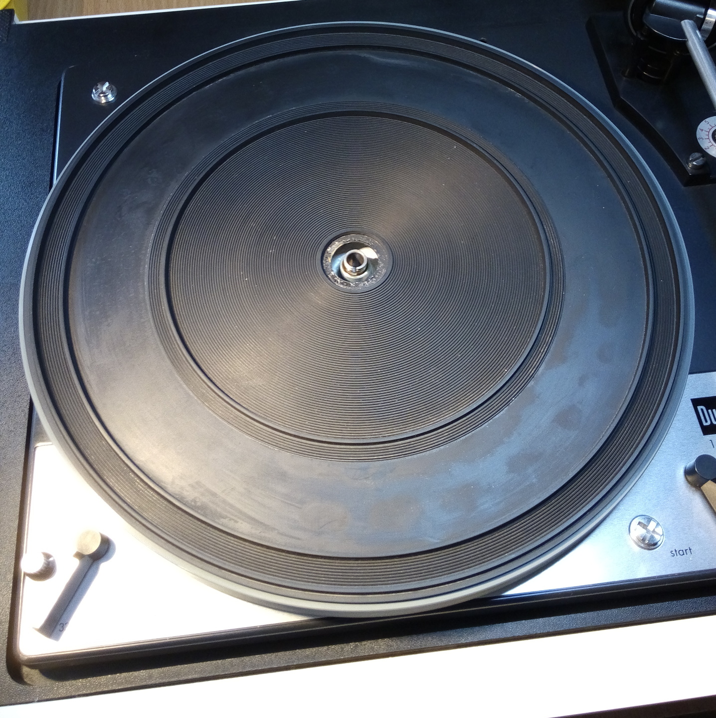
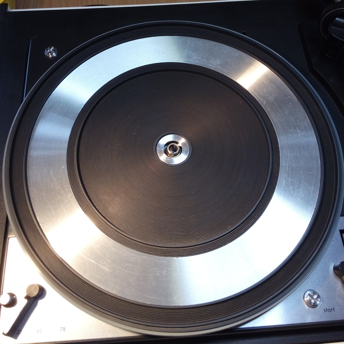
I started by removing old glue with white spirit and glued mat back to the platter with Vynil adhesive. The same one used for PVC flooring.It’s water solvable and comes off quite easily if needed. Remember to always degrease the inner surface of a platter from fingerprints before assembly!
Next, there was this annoying suspension problem. I don’t know if that’s just my unit or was it designed like that, but it really has too much compliance. Springs are very soft and have no damping, so table bursts into oscillation whenever you operate the controls. Sometimes it even forces stylus to skip. Putting damping material into springs, rectified this problem to some degree.

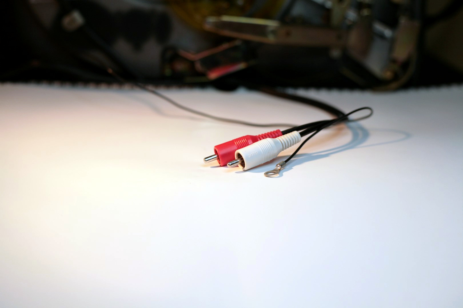
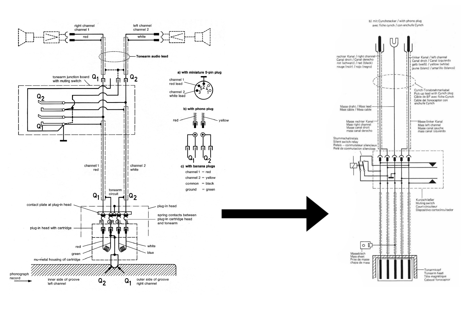
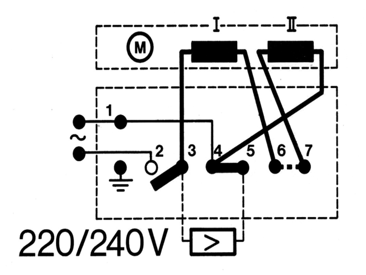
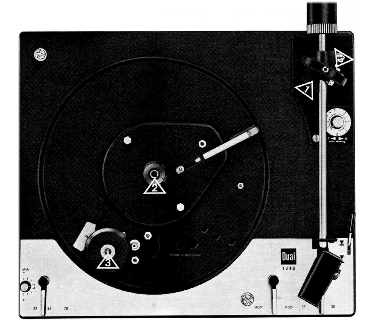
Update: I received quite a few questions regarding a wiring conversion to RCA standart. I thought that functional schematics from a service manual (3rd picture above) would be self explanatory, but it seems that a lot of my readers are having problems with it. So here you go – a more “visual” solution to a problem 🙂


Finally, it was time for a new wiring. I had low capacitance RCA wire lying around just for that. It was left from an upgrade I’ve done to a client, but you can tell it’s quality one just by reading Japan on it! Now again, whole grounding conversion and why it’s so important is really beyond the scope of this article and will have a separate one. Also, this write-up is getting really long, so I will just say that table came out dead silent.
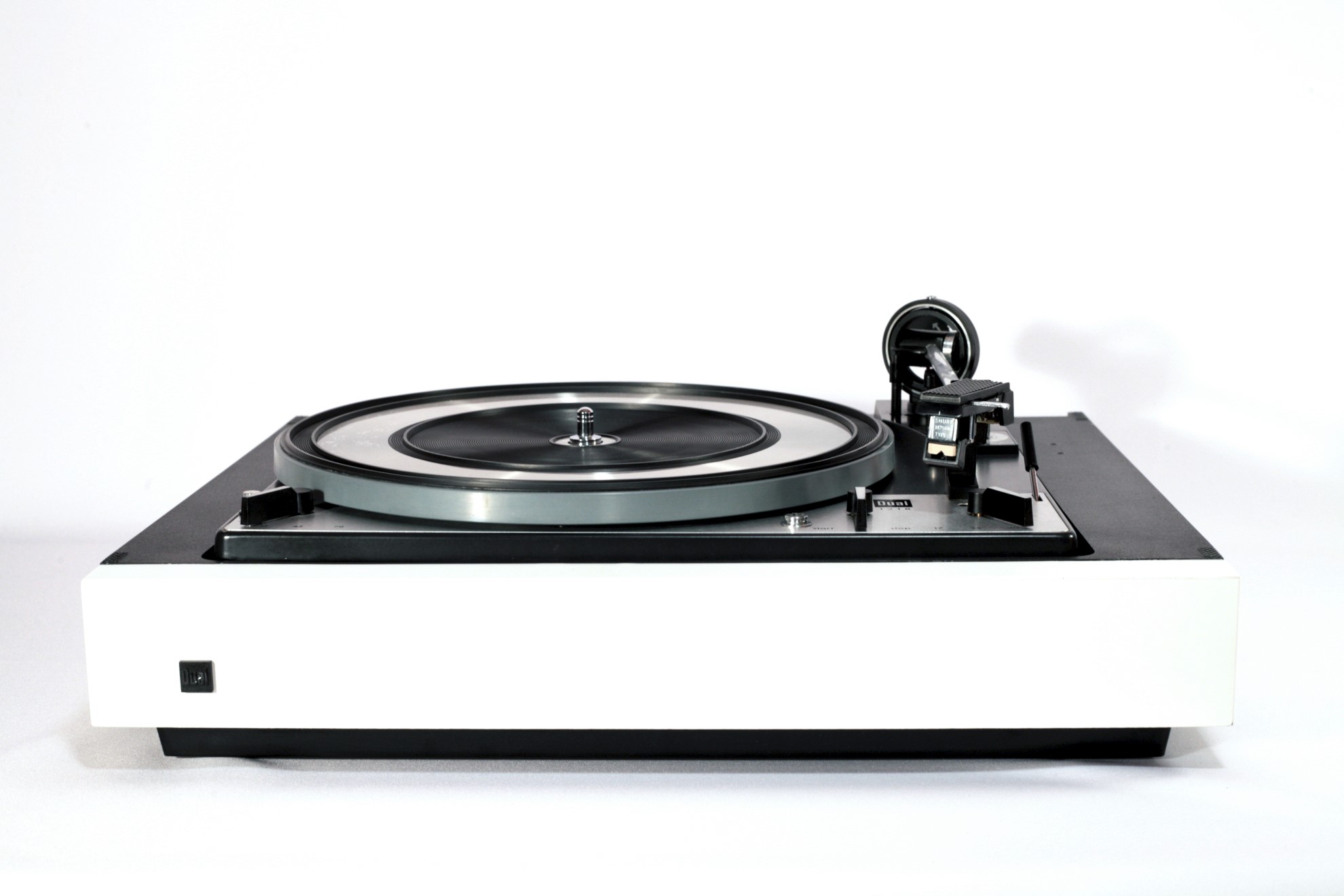


After all this hassle, I was really pleased with results. It looks good as new, and most importantly, works as one too. Actually, you know what? I might be bold and say, it’s now even slightly better!