1kHz Microphone Level Calibrator
Not all acoustical measurement software has a capability of entering microphone sensitivity data. And even then, there is an uncertainty regarding how well your audio interface is calibrated. Hence the most easy and reliable method of level calibrating your measuring rig is with some standard sound source. This could be just some well defined speaker driver mounted on a baffle. But setting up 2×2 meter baffle every time you need level-check is not exactly easy or convenient. So that leaves us with some kind of small closed-chamber construction.
Design considerations
The design of acoustical pressure calibrators has some clearly definable goals:
- Produce a stable, accurately known standard sound pressure.
- Minimize other parameters (noise, temperature, atmospheric pressure, etc.) influence to calibration process
First we got to choose SPL level and frequency at which we will operate. This level should be high enough to minimize outside noise influence (in case of calibrating in-field) and also be industry standard. That’s why most calibrators will have two SPL levels of 124dB and 94dB. First is useful for field use, when working in noisy environment, and second is standard microphone sensitivity measurement level. As for the frequency – 1kHz is standard for a lot of things in audio these days. And it’s also a 0dB point for all noise weighting curves. For stability and outside influence, we have a couple off different design approaches.


B&K Sound Level Calibrator Type 4230 block diagram
First one I would call passive calibrators. Above is a block diagram of B&K Type 4230 calibrator. This is a well proven design that is used (with bells&whistles) for the most calibrators up to date. As can be seen, volume of the front chamber will change with a diameter (and cap construction) of microphone under test. This will impact SPL level and produce large uncertainty. In order to negate this effect a clever scheme with back volume working into Helmholtz resonator is employed. Volumes of these cavities are selected such, that the resulting resonant frequency would be exactly 1kHz. Now the system will work into its resonance and will be insensitive to microphone diameter (or fitting) and outside pressure (Helmholtz resonator frequency depends only on chamber and neck dimensions). This leaves designer with a stable electronic oscillator task. Which was quite trivial even in the 70’s.


B&K Sound Level Calibrator Type 4231 block diagram
And the second ones are active calibrators. Like a B&K Type 4231 pictured above. As the part number suggests – it’s a more modern variation on the same theme. Here, instead of using passive means for stable operation, active components are used. Reference microphone directly senses the pressure of the front chamber and this signal is used as a feedback to set loudspeaker driving voltage. This way all outside variables are again negated and even better accuracy can be achieved.
My take on it
Was really simple. I just needed something to transfer my pressure-chamber generated level of 94dB to my mics more conveniently. And both of my measuring microphones are 1/4″. So there was no need worry about varying front chamber volume.

Technically there was nothing stopping me from introducing a second back chamber and tuning it to 1kHz. It’s pretty straight forward calculation. Although printing such “closed” part would be impossible without splitting it into two. But after some experimentation – I just didn’t saw a point. It should work just fine “as is” for my specific needs. So I went for closed back chamber. Don’t seal that hole wires if you planning to take it on plane. Otherwise it’s not a problem. Of course, I can only encourage a reader to do it properly.

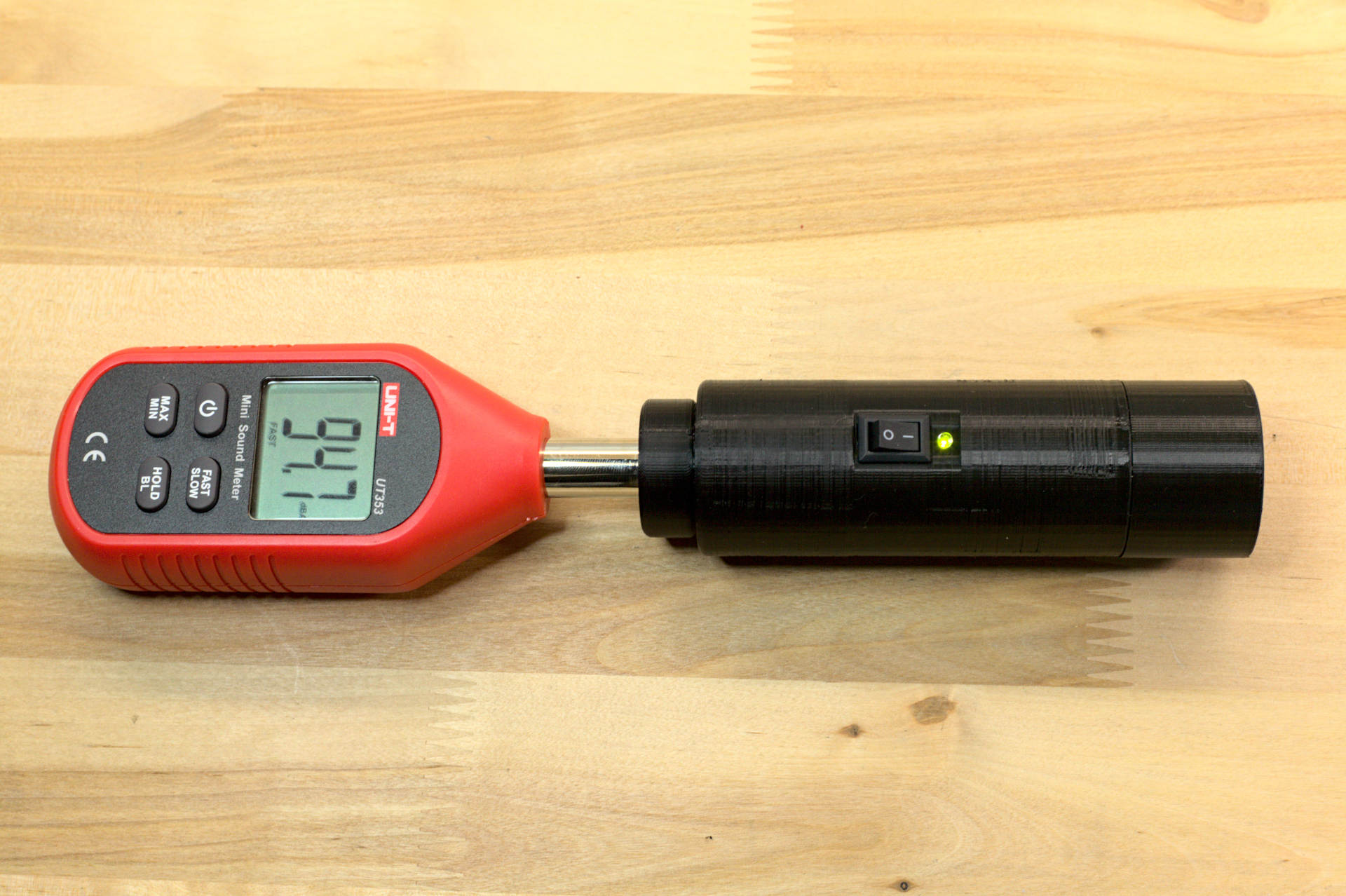
Here is my complete case 3D model. Bottom part is battery holder and accepts a standard 6LF22 9V battery. Middle part has an inside reliefs for PCB, cut-out for switch, front and back chambers and threads for mic adapter. Adapters are for 7mm, 12mm and 13mm microphone diameters.
Generator circuit
Here we are mostly interested in amplitude stability of the circuit. Distortion and absolute frequency stability is of the lesser importance. Below are a table with most common generator types and their resulting amplitude stability.
| Type | Typical Frequency Range | Typical Distortion (%) | Typical Amplitude Stability (%) | Comments |
|---|---|---|---|---|
| Phase Shift | 10 Hz–1 MHz | 1–3 | 3 (Tighter with Servo Control) | Simple, inexpensive technique. Easily amplitude servo controlled. Resistively tunable over 2:1 range with little trouble. Good choice for cost-sensitive, moderate-performance applications. Quick starting and settling. |
| Wein Bridge | 1 Hz–1 MHz | 0.01 | 1 | Extremely low distortion. Excellent for high-grade instrumentation and audio applications. Relatively difficult to tune—requires dual variable resistor with good tracking. Take considerable time to settle after a step change in frequency or amplitude. |
| LC Negative Resistance | 1 kHz–10 MHz | 1–3 | 3 | Difficult to tune over wide ranges. Higher Q than RC types. Quick starting and easy to operate in high frequency ranges. |
| Tuning Fork | 60 Hz–3 kHz | 0.25 | 0.01 | Frequency-stable over wide ranges of temperature and supply voltage. Relatively unaffected by severe shock or vibration. Basically untunable. |
| Crystal | 30 kHz–200 MHz | 0.1 | 1 | Highest frequency stability. Only slight (ppm) tuning possible. Fragile. |
| Triangle- Driven Break- Point Shaper | < 1 Hz–500 kHz | 1–2 | 1 | Wide tuning range possible with quick settling to new frequency or amplitude. |
| Triangle-Driven Logarithmic Shaper | < 1 Hz–500 kHz | 0.3 | 0.25 | Wide tuning range possible with quick settling to new frequency or amplitude. Triangle and square wave also available. Excellent choice for general-purpose requirements needing frequency-sweep capability with low-distortion output. |
| DAC-Driven Logarithmic Shaper | <1 Hz–500 kHz | 0.3 | 0.25 | Similar to above but DAC-generated triangle wave generally easier to amplitude-stabilize or vary. Also, DAC can be addressed by counters synchronized to a master system clock. |
| ROM-Driven DAC | 1 Hz–20 MHz | 0.1 | 0.01 | Powerful digital technique that yields fast amplitude and frequency slewing with little dynamic error. Chief detriments are requirements for high-speed clock (e.g., 8-bit DAC requires a clock that is 256 × output sine wave frequency) and DAC glitching and settling, which will introduce significant distortion as output frequency increases. |
Wein Bridge oscillator will fit our needs very well. And properly executed circuit will have 1% amplitude error. Which will result in 0.04dB SPL uncertainty. This is more then acceptable and will not be our design limiting factor.

1kHz Wein-Bridge oscillator circuit
Above is circuit I used in my project. Adjust R1 to center the frequency at 1kHz. Q1 can be any JFET with pinch-off voltage below 3V. Circuit needs about 30 seconds to fully stabilize after initial turn on. After that – amplitude stability is better then 1%. Output is set with 10kΩ multi-turn pot, which should be of a really good quality. Ideally one would replace it with fixed resistors after finding the right level.