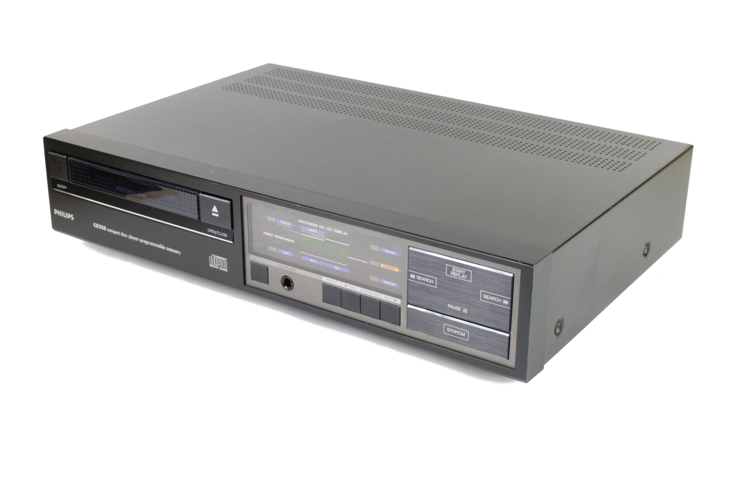

Phillips CD350 Restoration&Tubization
Looks are a deceptive thing, isn’t? If you look at CD350 and someone asks from what year is it, what you would say? Certainly not 1985. It looks newer, much newer. Like something from 90’s. But actually this thing goes back to digital roots as deep as it goes. Next stop is CD100 and after that probably some discrete wired R2R stuff on a development engineers table.
If you have browsed through digital section on this site, you probably noticed my affection towards TDA1541 DAC chip. I can trace this attachment to my first experience of a really good sounding CD player and as I later found out it was using Phillips chip-set. I always tried to listen to all kind of TDA1541 incarnations from as many manufactures as possible, but I never heard it’s predecessor. The one and only, precursor to all of them – TDA1540. Here is where CD350 enters the scene.


It came to me as “non-working” unit. It would start reading original CD’s in pristine condition once in a while, but nobody had enough patience to play with this old boy. It was obvious that laser is at the end of it’s life cycle and replacement will be needed. But I was not planing to use this player daily, so I had to try and make it read original CD’s again without lashing-out on expensive spare parts. After-all, I ripped all my CD’s long time ago and listen to digital only by streaming from my digital archives.
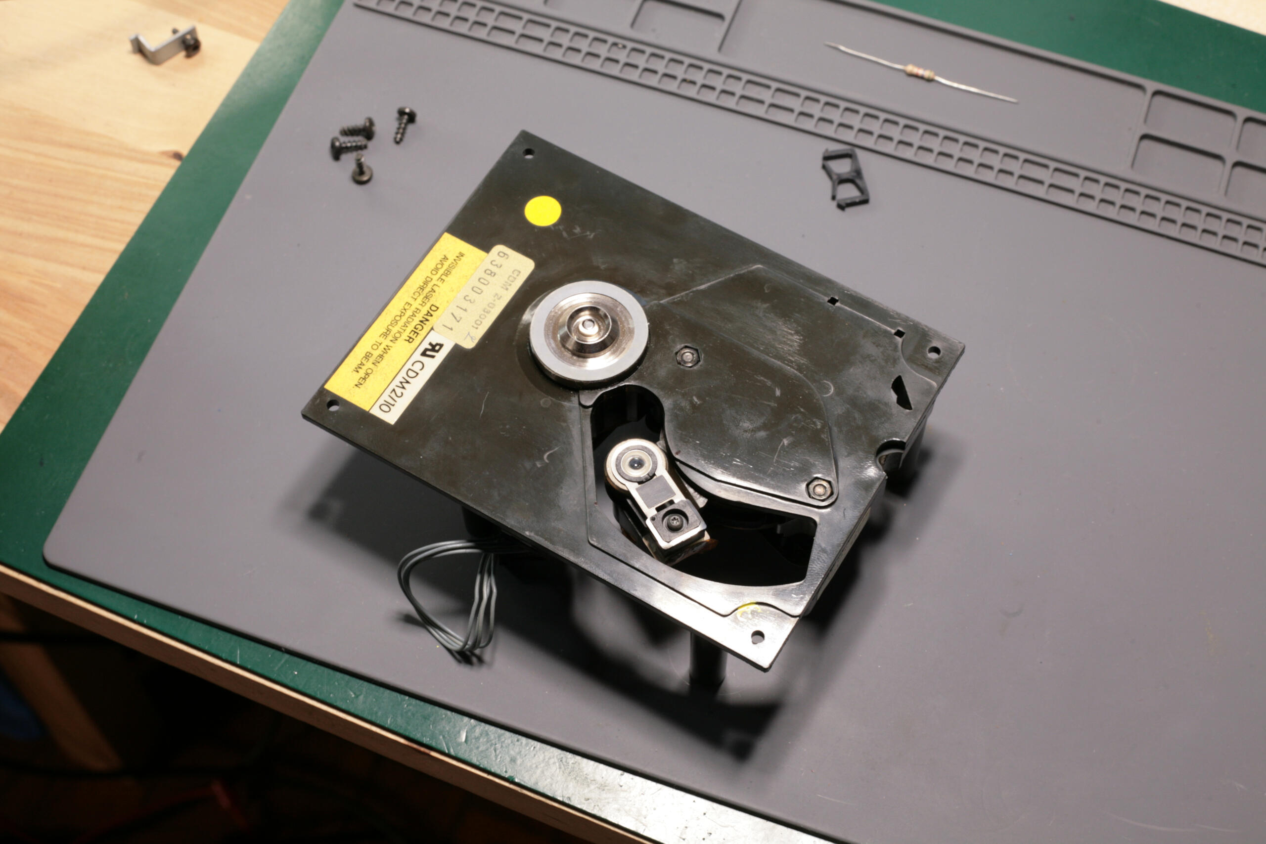
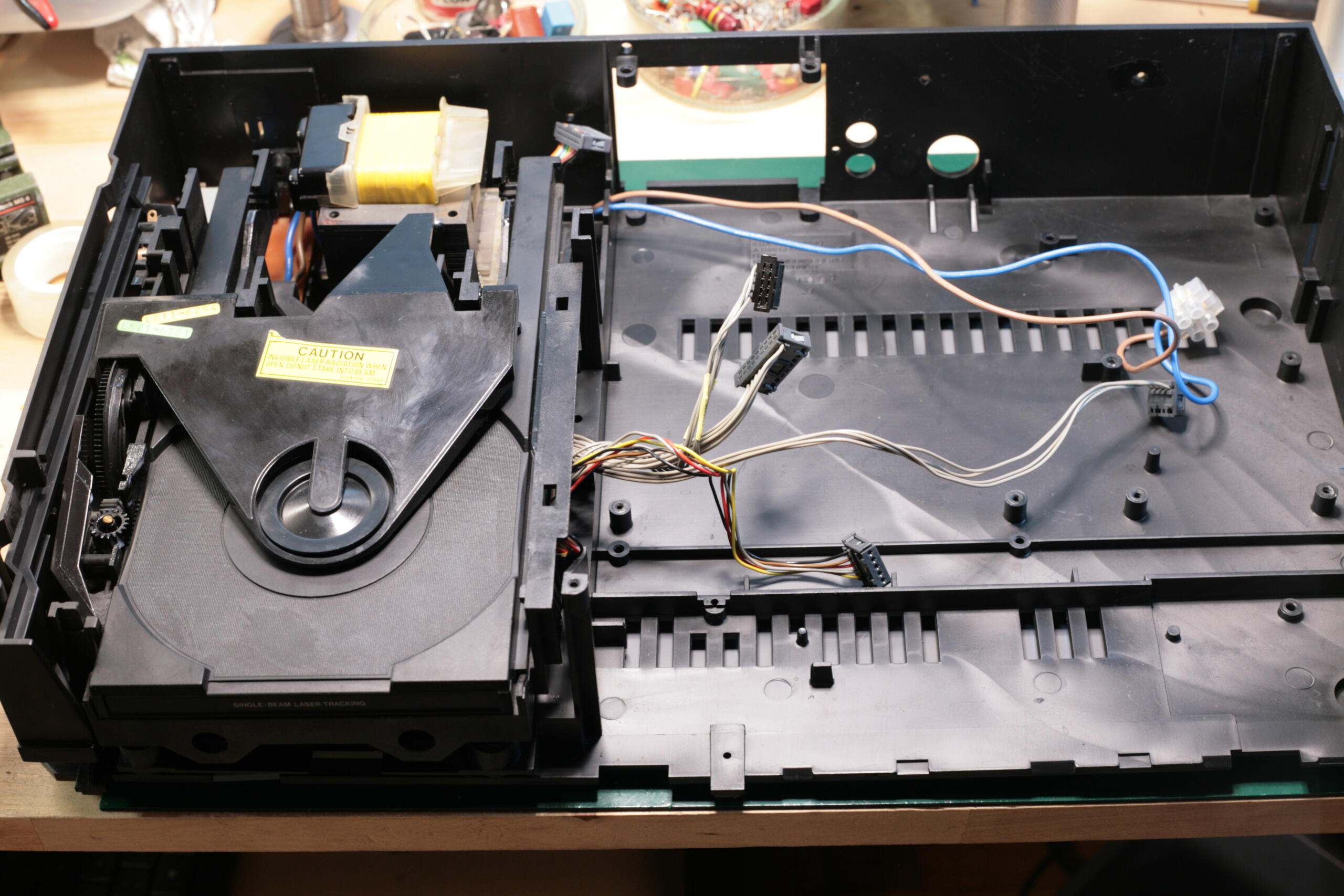
I disassembled the CDM2 transport and gave it a close inspection. This is just a hollow imitation of all-aluminum CDM1. Here almost everything is made out of plastic. This is all recurring theme through all of the CD350 parts. It’s straight obvious this player is made to meet the price point. Upon further inspection I found out that someone got here before me. Laser arm pivot screws were all outta whack and lens was not parallel to CD surface.
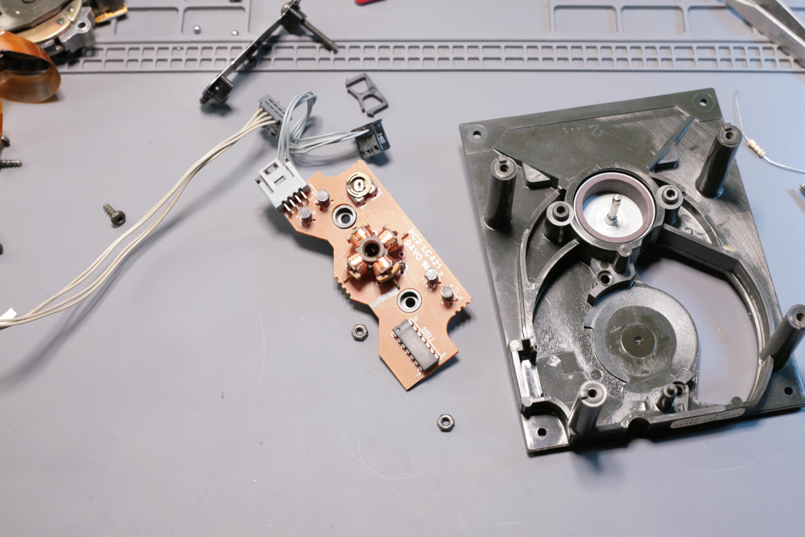


Someone already tried to “fix it” by doing “anything and everything” and probably all at once. Oh well, couldn’t expect anything else. I cleaned all parts thoroughly and lubricated both motor and laser arm axis. Watch out for those little ball-bearing balls on laser axis! They have a tendency to evaporate into trans-dimensional space without any prior warning at all.
Next the alignment procedure. Laser lens must be parallel to the CD surface. Trick with line on the transparent surface (doesn’t have to be disc) outlined in CDM2 service manual and here works pretty well. Also same method is in CD350 service manual but it’s in Dutch. Over the years I developed a better method that works for me better and I like to share it here.
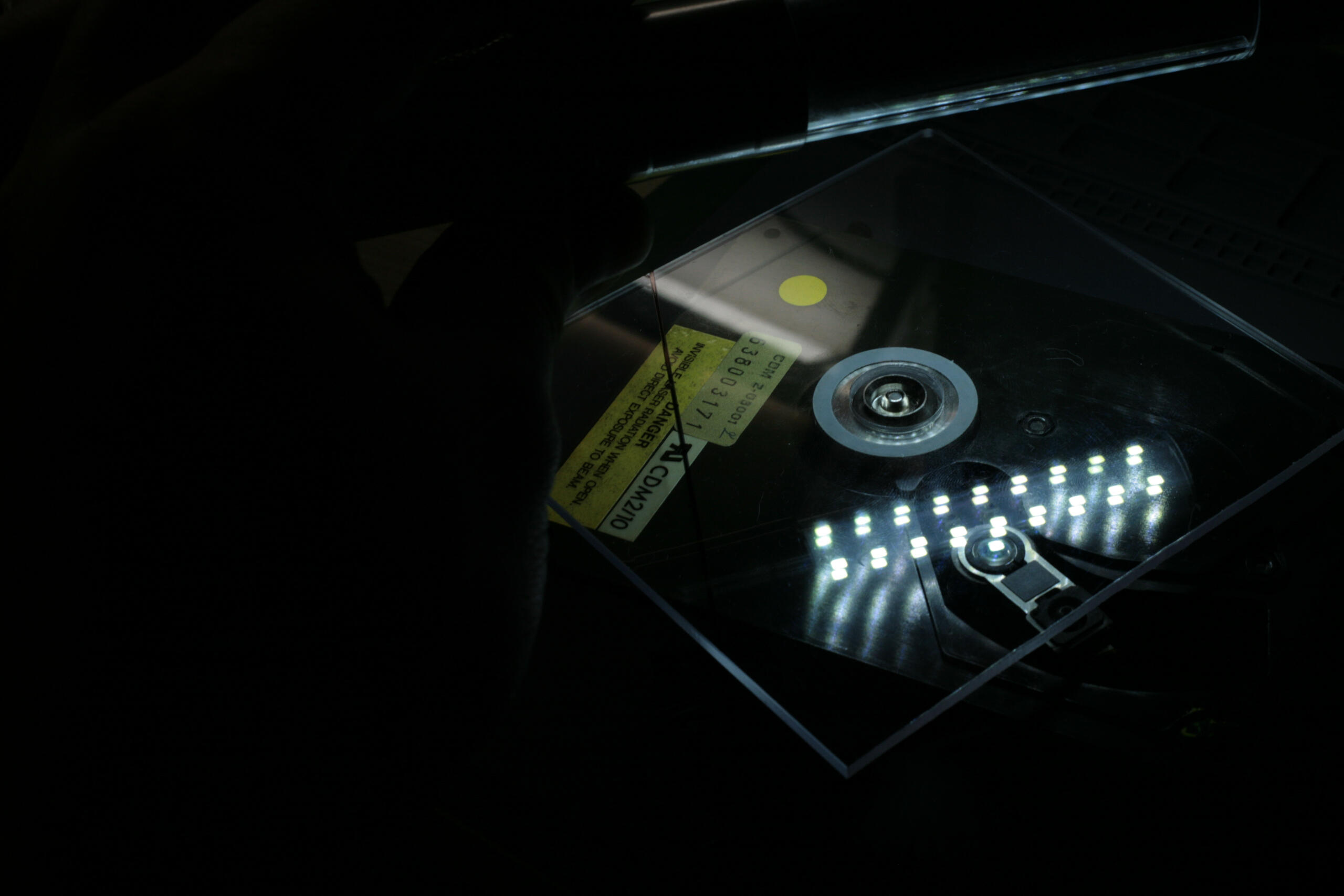

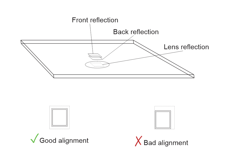
I think it’s very intuitive even without going into all parallax effect stuff. The main idea is this: if all the surface reflections are centered on one axis and symmetrical to each other, then all those surfaces must be parallel to each other. So you need some bright “point light source”. Square SMD LED works very well. Then you align your eyesight perpendicular to transparent media by looking how well both front and back reflections align. Now reflection on the lens shows how parallel it is to the disc surface. Adjust it at the center arm position by releasing bearing-plate screws, then check setting for both arm position extremes. I hope pictures above are pretty self-explanatory.

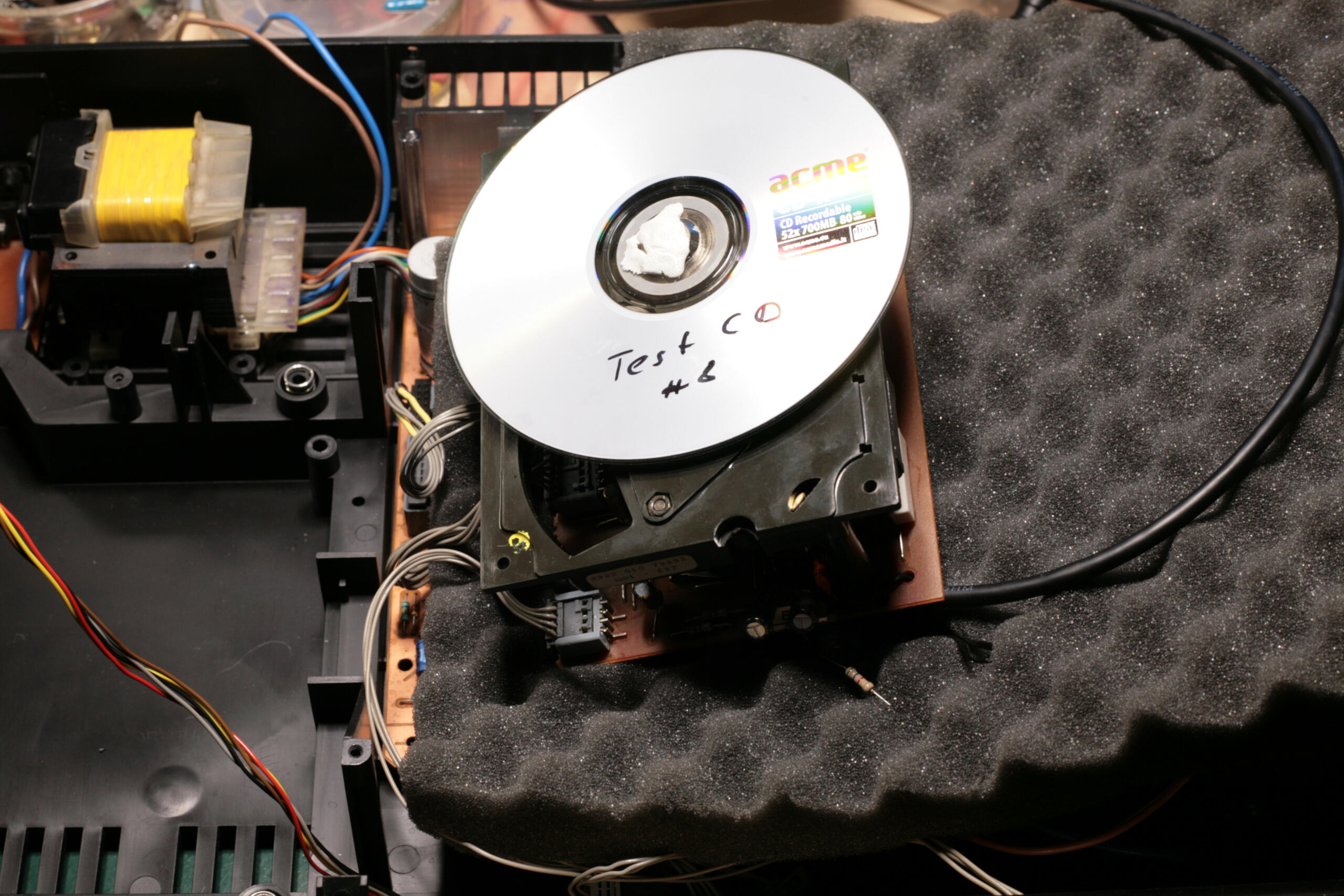
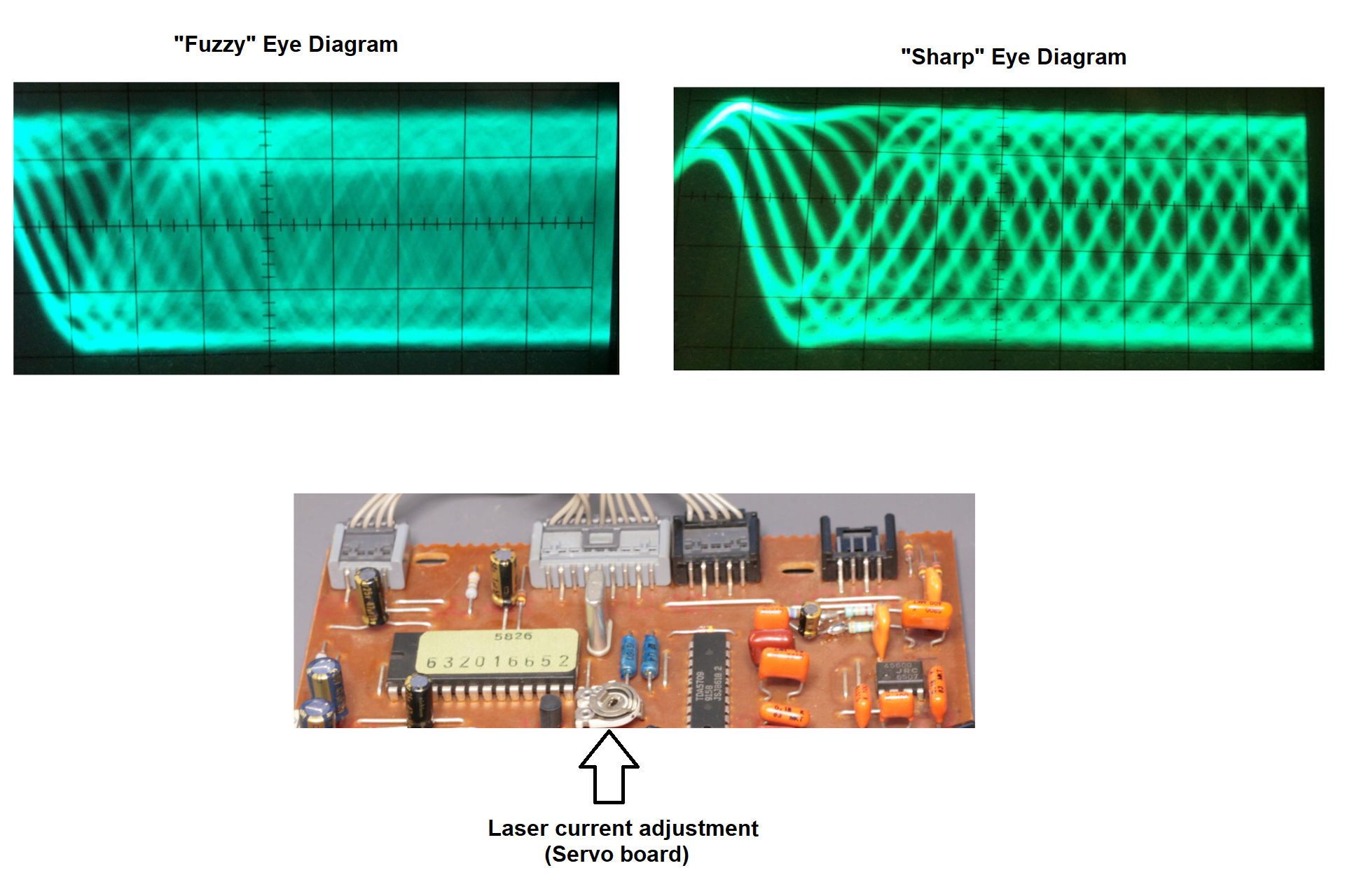
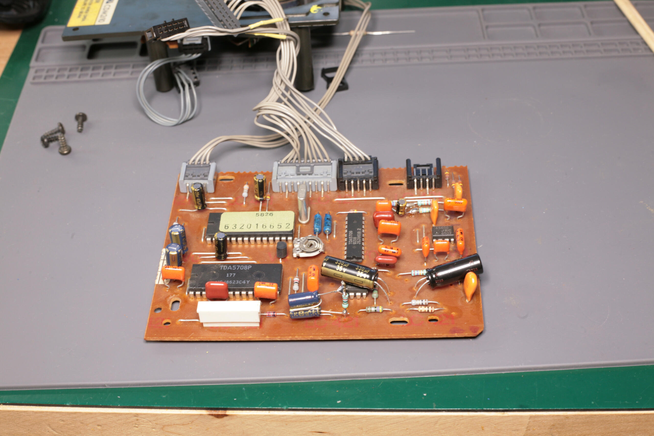
Now the laser current adjustment. This part is absolutely crazy on 350. You must access adjustment potentiometer on servo board only from below! There is a special hole on PCB. So whole transport mechanism must lay on it’s side. This of-course upsets the laser arm movement because of gravity. And CD is always trying to fly away, so you must stick something on the center shaft. And on top of that you should be able to probe the HF output signal! Using what part of your body I would like to ask? This is madness…
I soldered RG-174 cable through 1kΩ resistor to PIN27 (HF_OUT) of TDA5708 and terminated other end of the cable with 50Ω load. What I made here is 1GHz probe for 10$, very cool trick that I learned many years ago from “A Handbook Of Black Magic” by Johnson and Graham. Absolutely recommended read for anyone trying to wrap their heads around digital stuff. Now I could adjust HF eye diagram from “fuzzy” to “something acceptable”. I used a plain CD-R with some test tracks on it. No need for “special” discs, eye pattern will be the same no matter what data is on it. CD-R has much worse reflectivity, so if you manage to make it playable, then all factory pressed discs will work like a charm.


Time for the usual recap. For CD350 this is not a chore. Just 3 boards and handful of capacitors. I really don’t get people saying, why do you change all caps if most of them are probably fine? When talking about all the “non-audio” retro gear I think I would agree. If it works – it works, don’t burn your time and money. But for audio gear… man, you must be joking, right? If somebody can’t hear difference between fresh, modern, low-esr caps and 40 year old dried placeholders, then I have a bad news for you buddy. It’s probably a time for a new hobby.

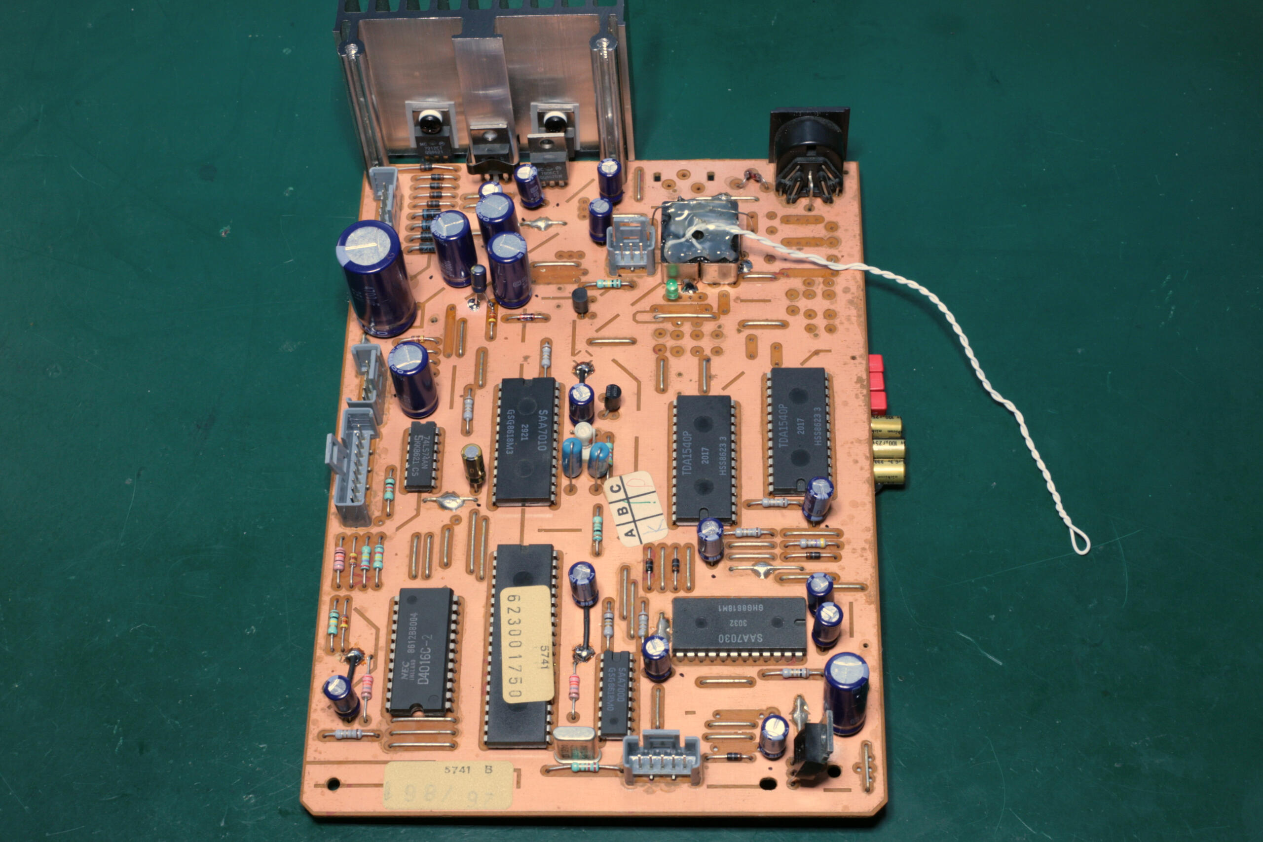
I swapped mains transformer connection from pin5 to pin14 as per CD350 service manual to rewire it for 240V. Despite that ±12V regulators where still sitting at +70°C. Why they are not on a heat-sink originally? I don’t know, but I have corrected that. DEM caps where swapped for 1uF and 0.1uF film caps by WIMA, and I additional decoupled all TDA1540 power supply lines with 100uF Nichicon Gold’s. Muting relays are connected same way as in CD304 and provide 30s turn-on delay.
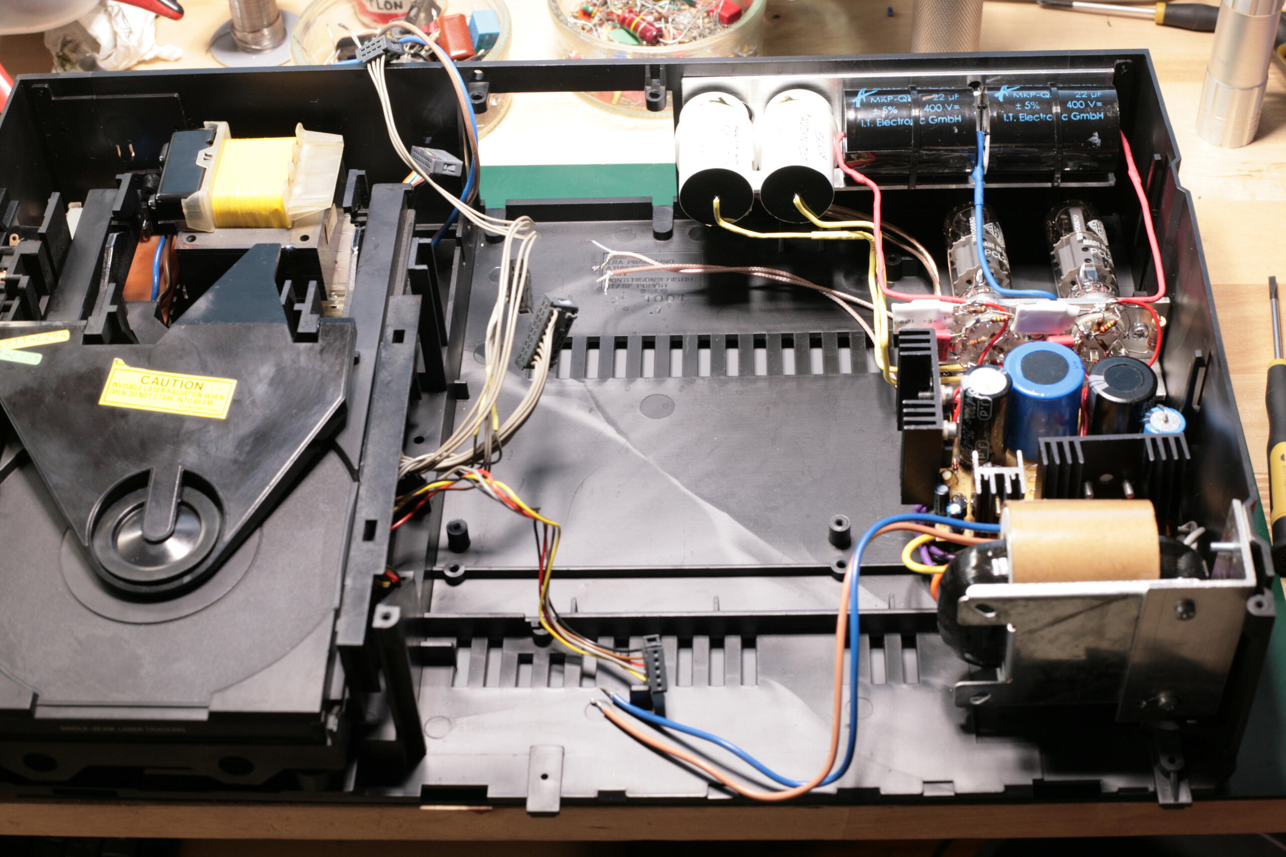

One very positive thing about CD350 is the abundance of a free space. You could fit a tube radio receiver in there! And it would still be space left for I/V circuit. This was a nice change from claustrophobic CD304. I even used existing plastic rivets to fix everything into place with screws, nice. It’s like it was meant for “tubization”. Is that even a word? Not sure.
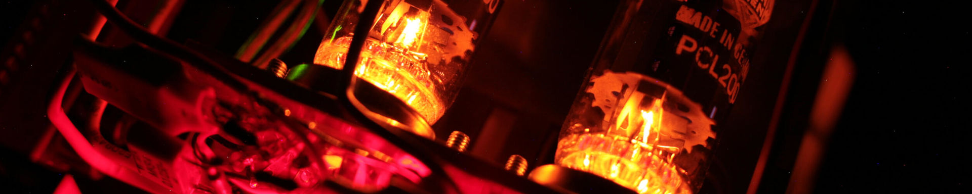
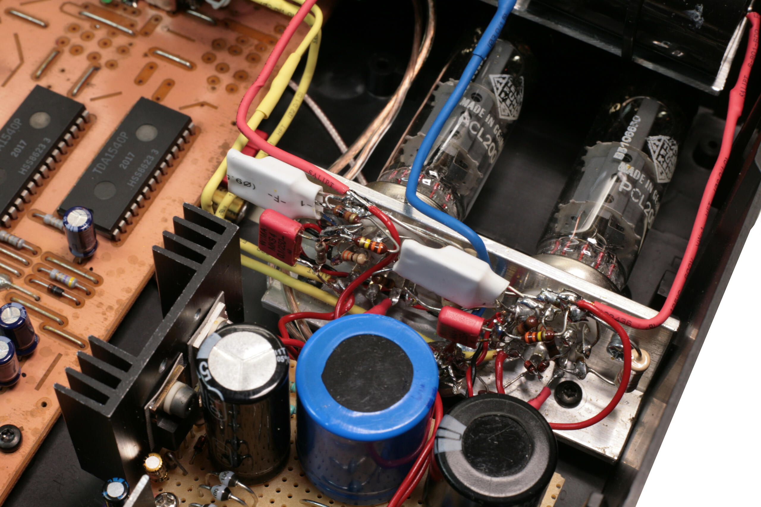
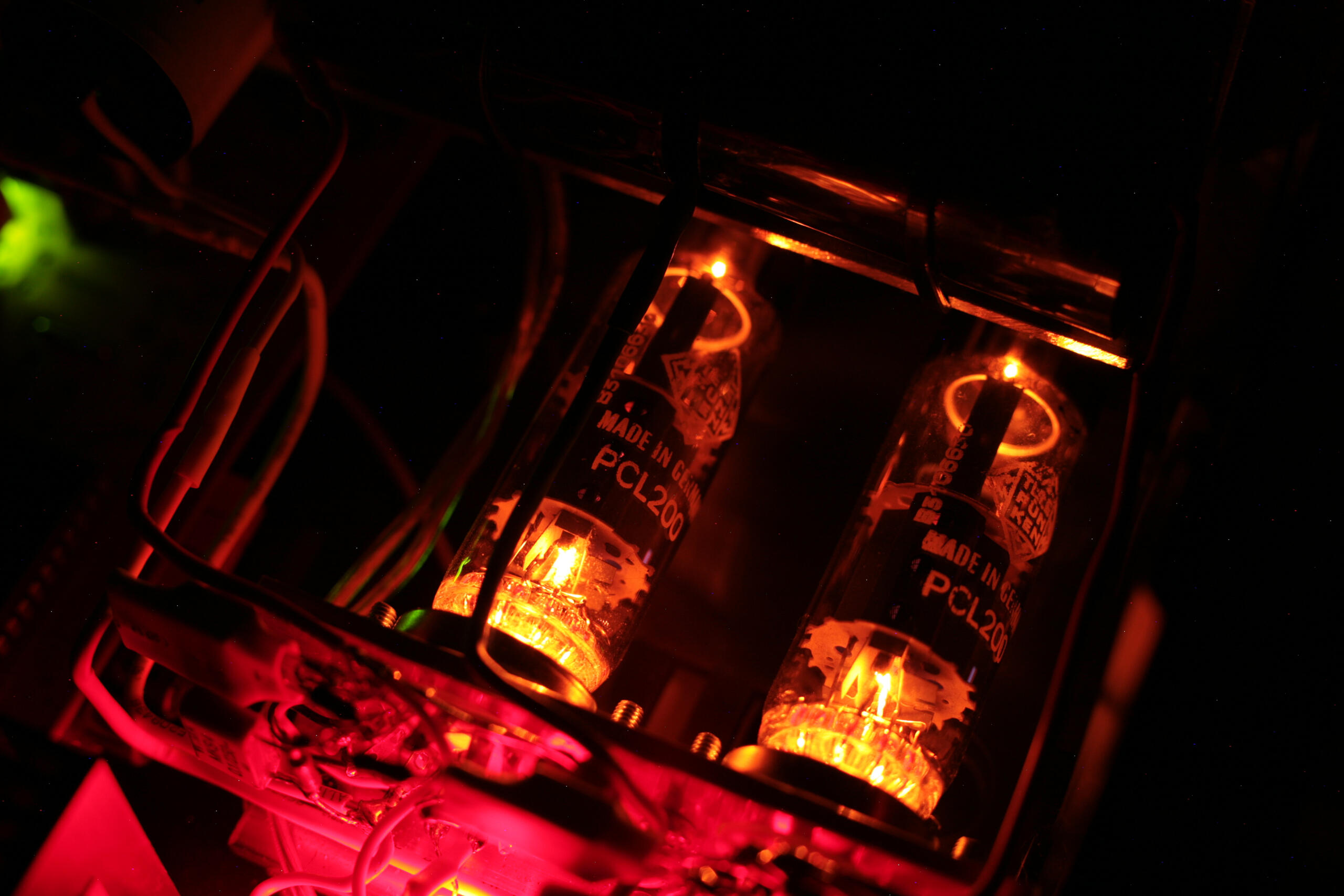
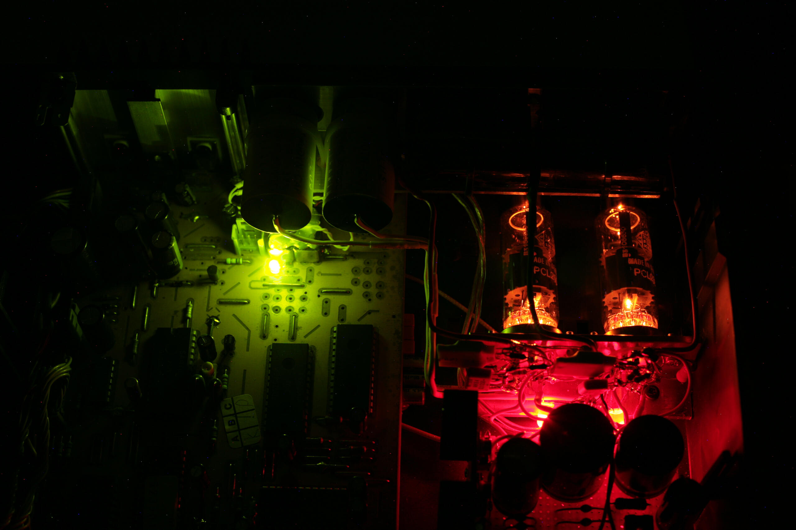
At the heart of this project we have PCL200. Probably most linear Pentode/Triode out there. At least from the ones I have measured. It is quite a modern tube, designed and produced in late 60’s for color TV sets. Marvelous sounding triode or triode-strapped pentode and still pretty cheap. Just don’t tell anyone! Or it will become second D3A 🙂
It is mostly overlooked because of non-standart heater voltage of 15.5V. I don’t get what’s the issue here, as even the most cheapest “DAC project” Chineese R-Core transformers can be rewired for 15.3VAC by connecting 6.3V and 9V windings in series. Usually 9V windings are rated for 0.2-0.3A, so two in series must be connected for 0.6A 2xPCL200 heaters. I don’t like AC heating, mainly because of all the additional mains noise. Even indirect heating tubes have non ideal heater isolation and all the wiring with high-current AC voltage makes it even worse.
Above is schematics with simple “voltage-soft-start” for heaters at 15.5V. It limits the turn on current and extends tube life by a lot. High voltage are regulated by IRF840 capacitance multipliers. All IRF840 mosfets can be replaced with STF5N80K5. It has isolated TO220FP package and integrated gate protection, then 18V zener diodes from schematics can be omitted. Tube triode is a simple LED biased gain stage for 33Ω I/V resistor and pentode is triode-connected and works as cascoded-cathode-follower. This is my go-to circuit for driving cables and this particular ones has 59Ω measured output impedance! Q1 is constant current source and can be replaced with DN2540@10mA. Adjust C9 for your pre-amp input impedance (1.5uF is fine for 100kΩ, 4.7uF for 50kΩ), C4 can have as much capacitance as your pocket allows. These two caps has most influence on sound quality so don’t cheap out on them.
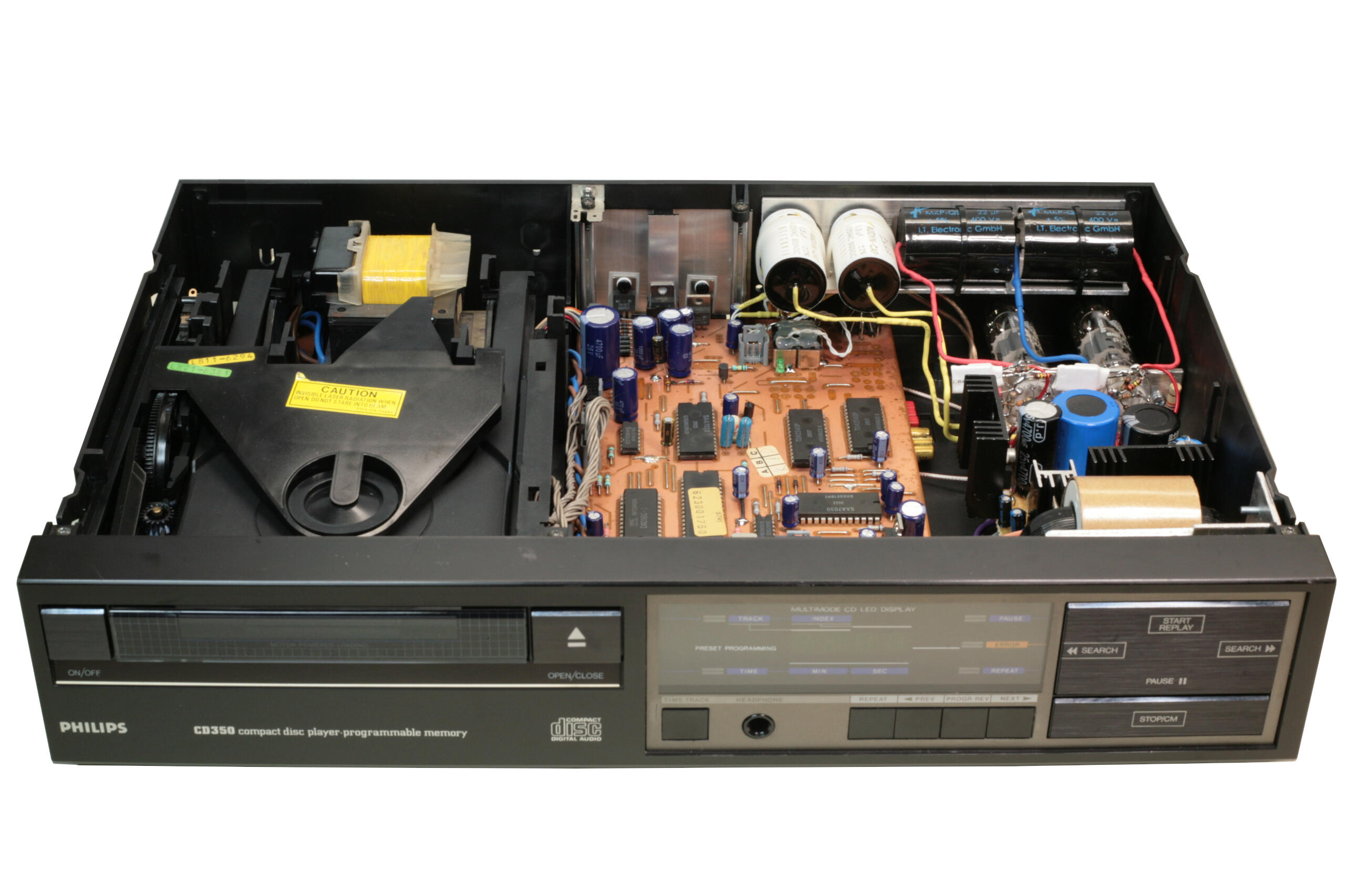


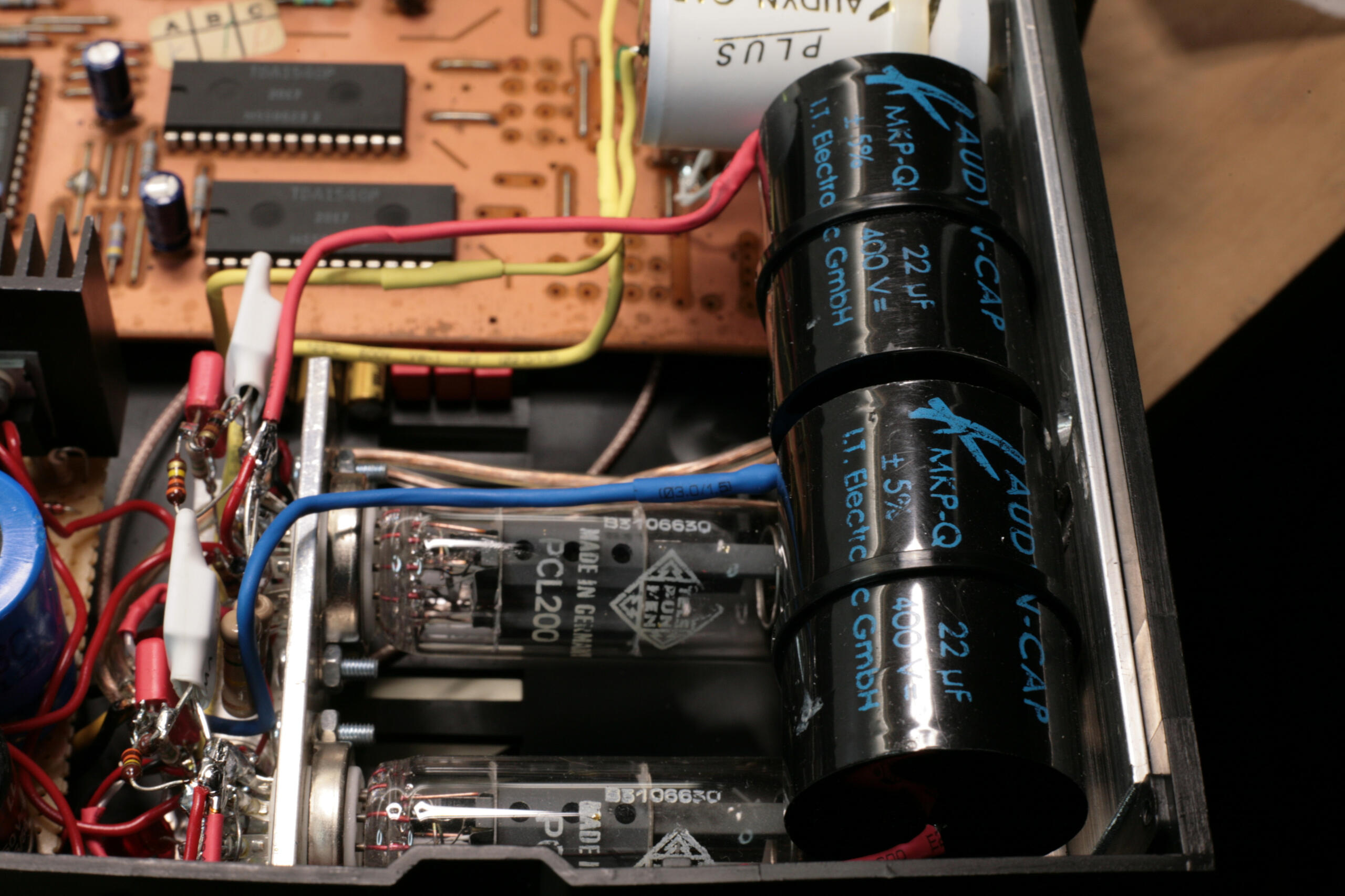


Looks almost like it came from factory like that, doesn’t it? Ok, ok… I should’ve made a real “home brew” power supply PCB to give it more authenticity. Now that proto-board is a dead-giveaway 🙂 All in all, this was a piece of cake to make in comparison to CD304.
Couple words about sound and measurements. I post distortion spectrum in all my projects just because I always do a sanity-check. If something is wrong with tubes, bias point or whatnot, distortion spectrum will show that. This however will not tell you anything about the actual sound as there is much more to it then harmonic distortion.

TDA1540 distortion spectrum at 0dBFS and -12dBFS
Over the years I have watched hundreds of these spectra and I learned to directly associate some properties to things I actually hear in music. One thing that always annoys me and sounds dreadful to my ears is 7th and 9th harmonic distortion. I seem to be able to detect it at ridiculous levels of -100dB or even below that on some specific cases. One exception is an monotonically falling spectrum like in tube amps. Then those high order harmonics are successfully masked and everything sounds just natural.
Unfortunately TDA1540 has quite a lot of high order harmonic distortion. This has nothing to do with I/V stage, DEM caps or anything else. It’s intrinsic to this chip itself. And it doesn’t get any better with an output level. Usually all DAC’s have trouble at full scale 0dBFS, but then distortion falls down. Unfortunately not for TDA1540. Most probably it’s the result of only 14-bit resolution and high zero-crossing settling time, but I’m just speculating.
I wouldn’t say it’s a deal breaker, but this DAC just sounds very raw. Some might say more “analog” but I would disagree. I listen a to a lot of vinyl and reel-to-reel tapes and TDA1540 is nothing like that. Sound is a little bit edgy and lacks the easiness and effortlessness of later TDA1541(A). This comes from direct A/B comparisons with CD304 having almost identical level of modifications. If there was nothing to reference it, I could probably get use to it and really enjoy. Given that the rest of the system was tube based and very relaxed-sounding.
There is a couple things that might help to mitigate that. First idea would be to increase the I/V resistor to 50-60Ω. This will increase all other harmonics and might help to mask high-order ones. Also one could try to introduce some random thermal noise in an output stage and use it as a dither to “drown” everything below 90dB in that noise floor. Imagination is a sky here. But for now, I will stick to my TDA1541.