My very first DIY: Vifa 2-Way Floor-stander
This is how it all started. It’s somewhere around year 2005. Winter. I bought another set of speakers and experienced another major disappointment. This was TANNOY Mercury F3 if my memory serves well. They were in a mint condition although slightly used pair and I wasn’t able to listen to them before buying. Well, apart from the usual “look, they work!” at the seller place. Then I came home in a middle of a winter storm with these damn things on my back. Disconnected my old paper-box Technics SB-L95’s, that these marvels of new-era engineering was bought to replace, and set for a listening. And just after a couple of songs I thought I will explode from frustration. How the hell these new speakers, that I paid maybe half of my months salary, sound worse then couple old Japanese launch boxes?

So this was a breaking point for me. I knew right there and then that I had to start getting into speakers. In a major way. I don’t want to be customer anymore and eat what is served. I want to be able to build my own speakers one day. And be competent at proper technical analysis and design workflow. I want to know what makes speakers sound good or bad and how all that correlates to measurements. And I wasn’t delusional about it. I knew it won’t happen in a day or two.
The journey begins
I spend next couple of years reading everything I could get my hands on regarding these subjects. Every day after work I would sit and browse audio forums, diy sites and hunt for more e-books to read. It became my controlled obsession. If I was hard pressed to name only two books to read on the subject, these would be The Loudspeaker Design Cookbook by Vance Dickason and Testing Loudspeakers by Joseph D’Appolito.

They contain ~90% of what there is to know. Other 10% is experience and know-how. And these 10% are what it’s all about. They ultimately separate mediocrity from exceptionality. They are most difficult to obtain because of the financial burden associated with speaker building. It’s not an amp or DAC, were components cost cents (although that can get expensive too). We are talking of hundred of dollars just for ok drivers and as a rule of thumb -if your project budget is less then ~1k$ – it’s a good chance you’re better of just buying something. This situation is somewhat mitigated by online DIY community which is sharing information freely. But in such a subjective area as audio reproduction it has it’s constraints.

Best online DIY resources back then were Troels and Zaph web pages and diyaudio.com forums. In no particulate order. I don’t follow situation that closely now, so maybe something new and worthy came up recently.
It’s time to build something
So it’s a spring of 2007 and I feel ready. But I’m not there yet. I know all in’s and out’s of theoretical speaker engineering, but there is no way I would attempt my first build from scratch. So I set my budget limit to ~600€ and went for a project hunt. At around this same time Troels Gravesen was already a well known and respected speaker designer. At least in a DIY circle. His designs are well thought-out, executed and documented. I can’t find any faults in his techniques. At least on a theoretical level. So I decided to play safe and go with one of his proven designs.

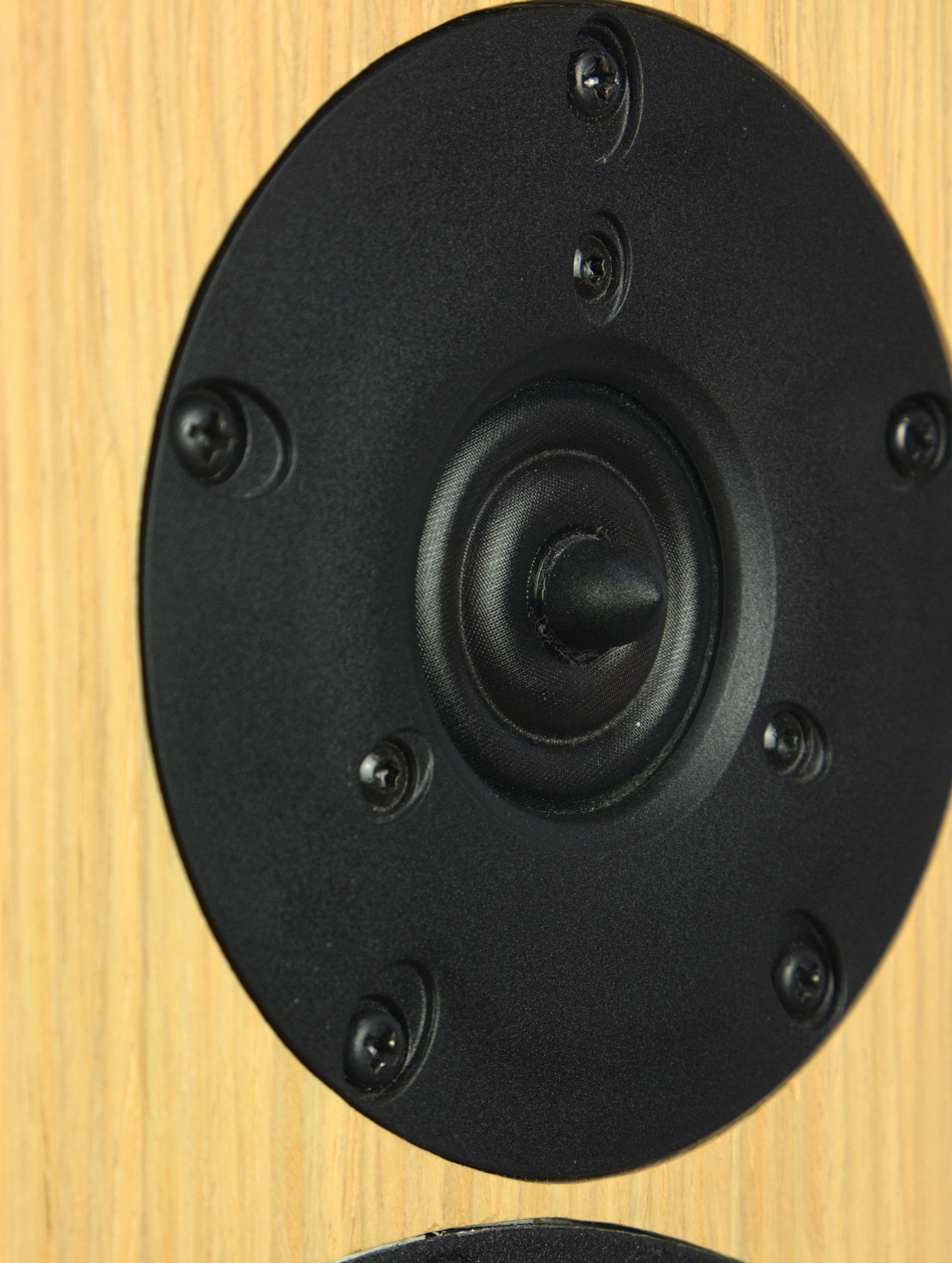
With my budget options were limited to a 2-way design. I had a chance to listen to HDS134 and was really blown away by the performance of such a relatively cheap driver. So I had confidence in Danish audio driver manufacturers and was choosing between Peerless and Vifa designs. I choose Vifa mainly because of a larger membrane area. There is no replacement for displacement when it comes to bass performance. XT25TG tweeter and the whole concept of “ring radiator” was something new to me though. So I bite the bullet and made online order.

After couple of weeks my carpet was growing full of Danish goodness. Now we are talking!
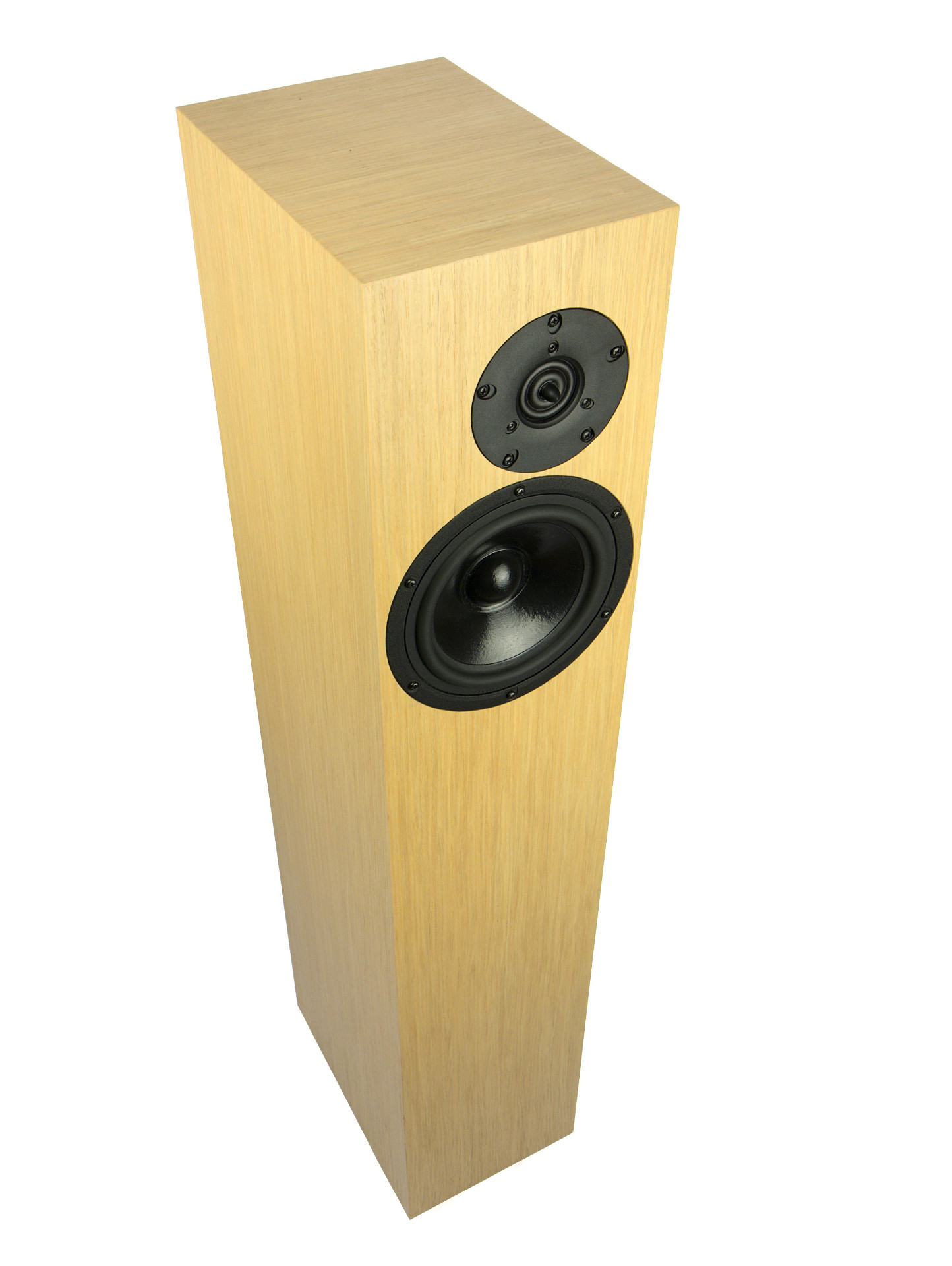
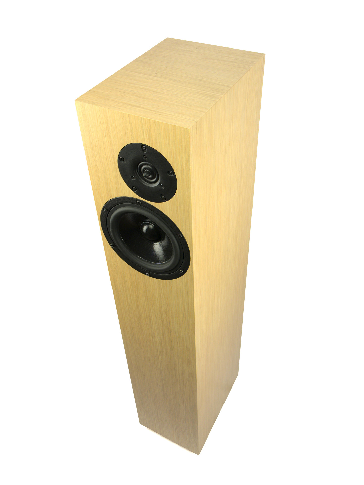
That warm wood
It’s time to build new homes for these drivers. And this is the strongest argument in favor of any DIY speaker – woodwork. If you have skills, time and a little bit of money for raw materials – you can do a better job then 99% of commercial speakers do.

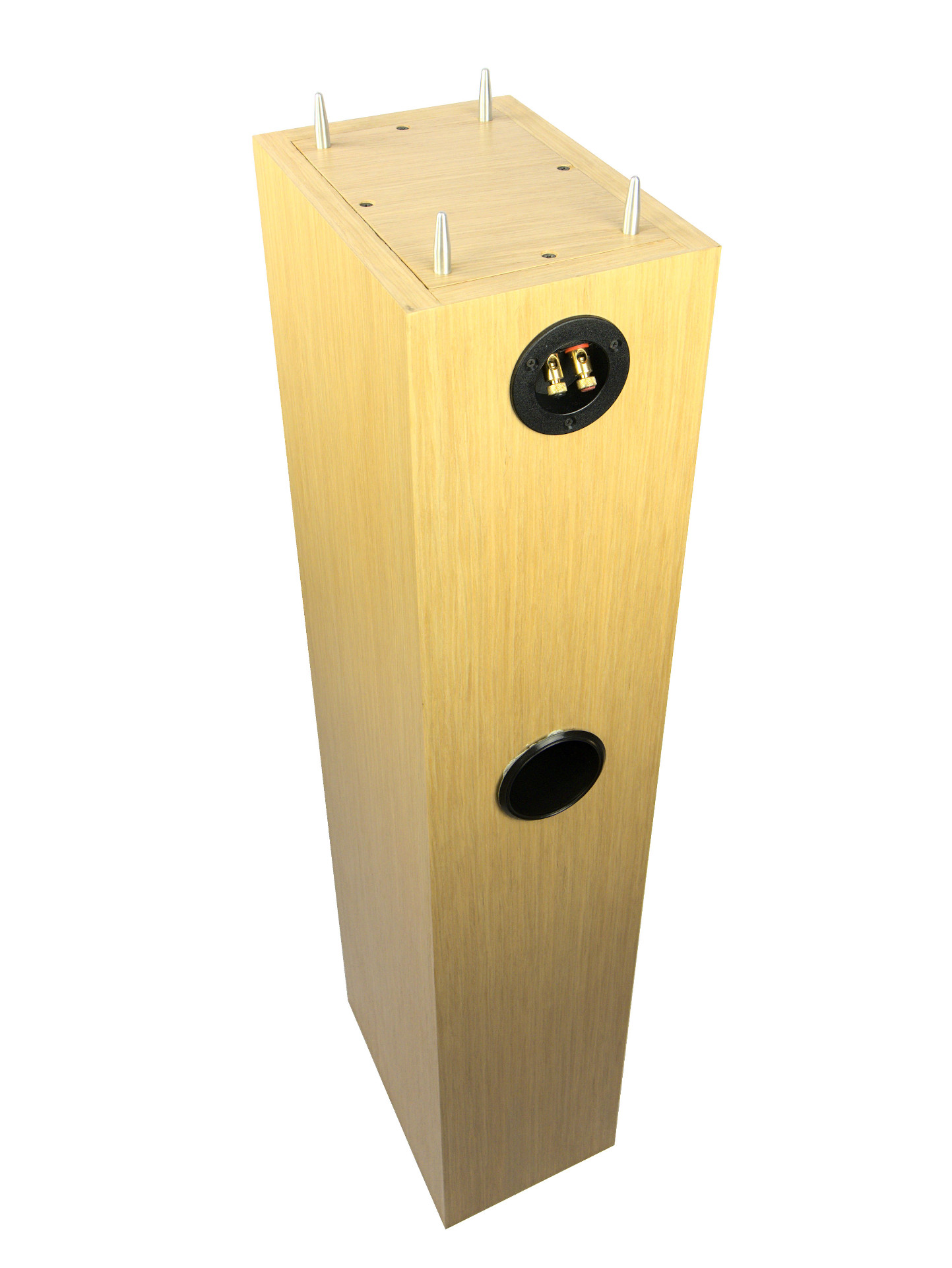
Here is a 3D model for these speakers that I made using Google SketchUp. Just because… that sinking feeling when you take your freshly cut parts and realize that they don’t fit is so overwhelming. Material I used was a 27mm Baltic Birch plywood for front and rear panels and 21mm of same plywood for everything else.
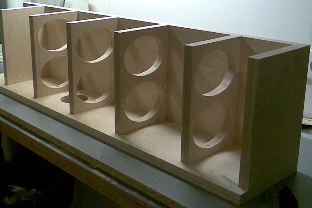


And the real work started. Parts were cut on a CNC machine so everything was tight and square. There is a lot of controversy about how you should join parts together. There is screws camp and glue camp. My answer? Use them both. Apply glue and tighten with appropriate wood-screws. No need for a gazillion of large clamps to apply a steady pressure then. Amount of damping material and its application is always more or less guesswork. I just followed general guidelines from original design.

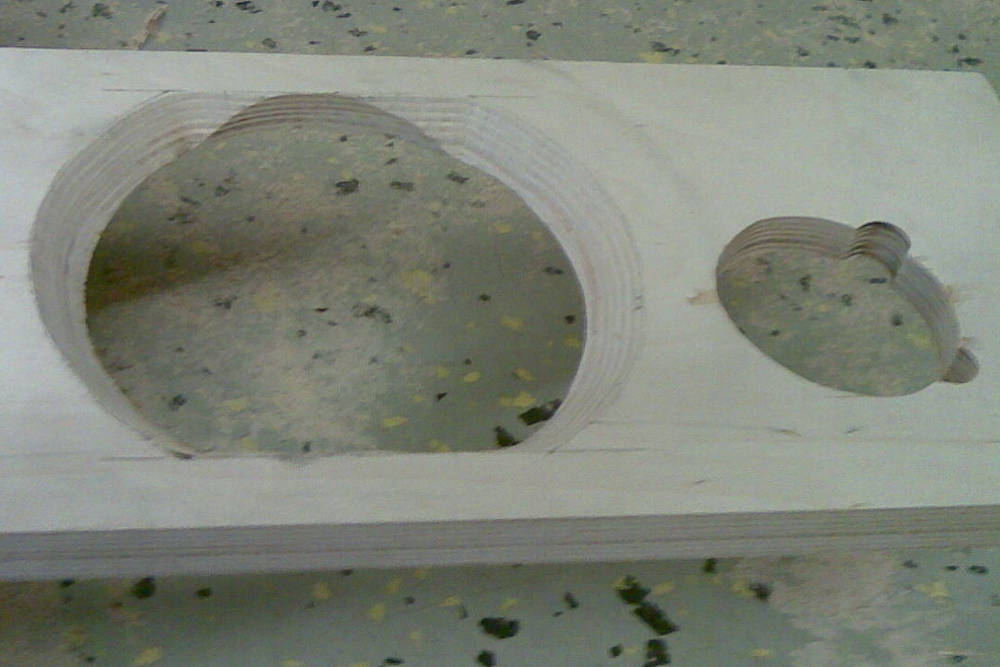

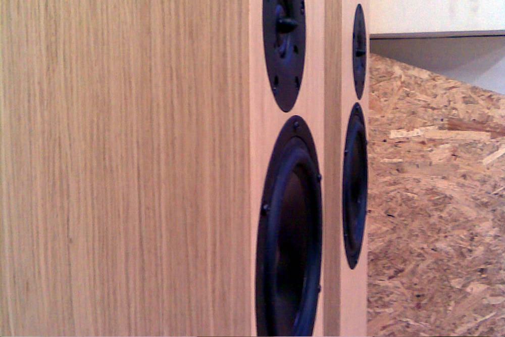
Then there is a front panel drivers fitment. It’s not that easy to flush fit a driver, but after some practice – it’s doable. Just don’t practice on a real front-panel. And don’t forget to chamfer the back-side. It’s not for esthetics. Sharp corners near back of the membrane creates real and measurable problems.


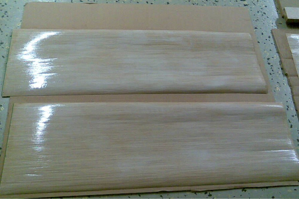
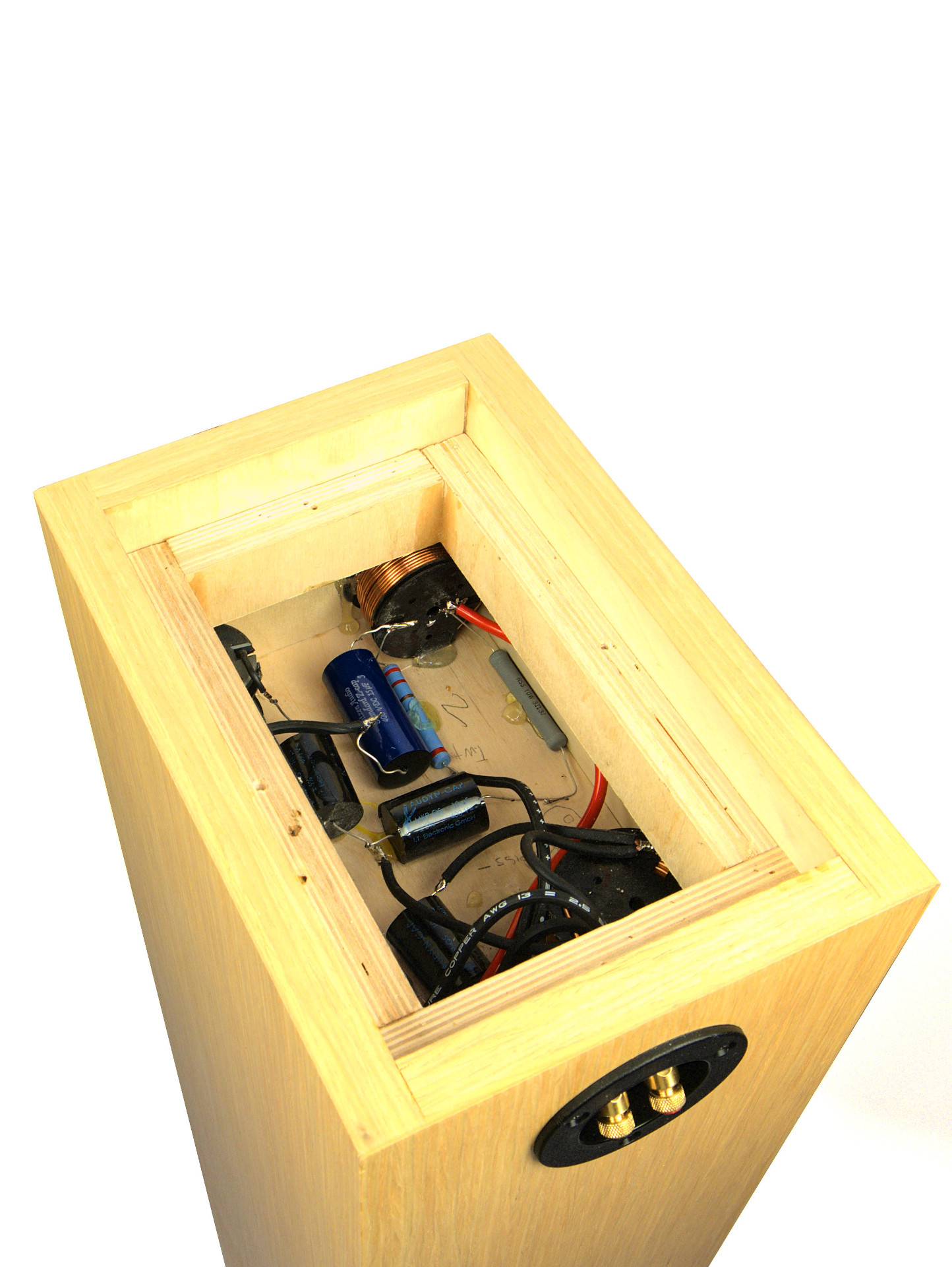
I decided to assemble the crossover-network together with cabinets. As I later found out, this was not the smartest idea. Although it’s a simple network when compared to electronic schematics, nevertheless this job should be taken with more care. Some auto body-filler for screw masking and we are ready to go for ash tree veneer. I applied pre-cut veneer sheets using hot-press method.
The result
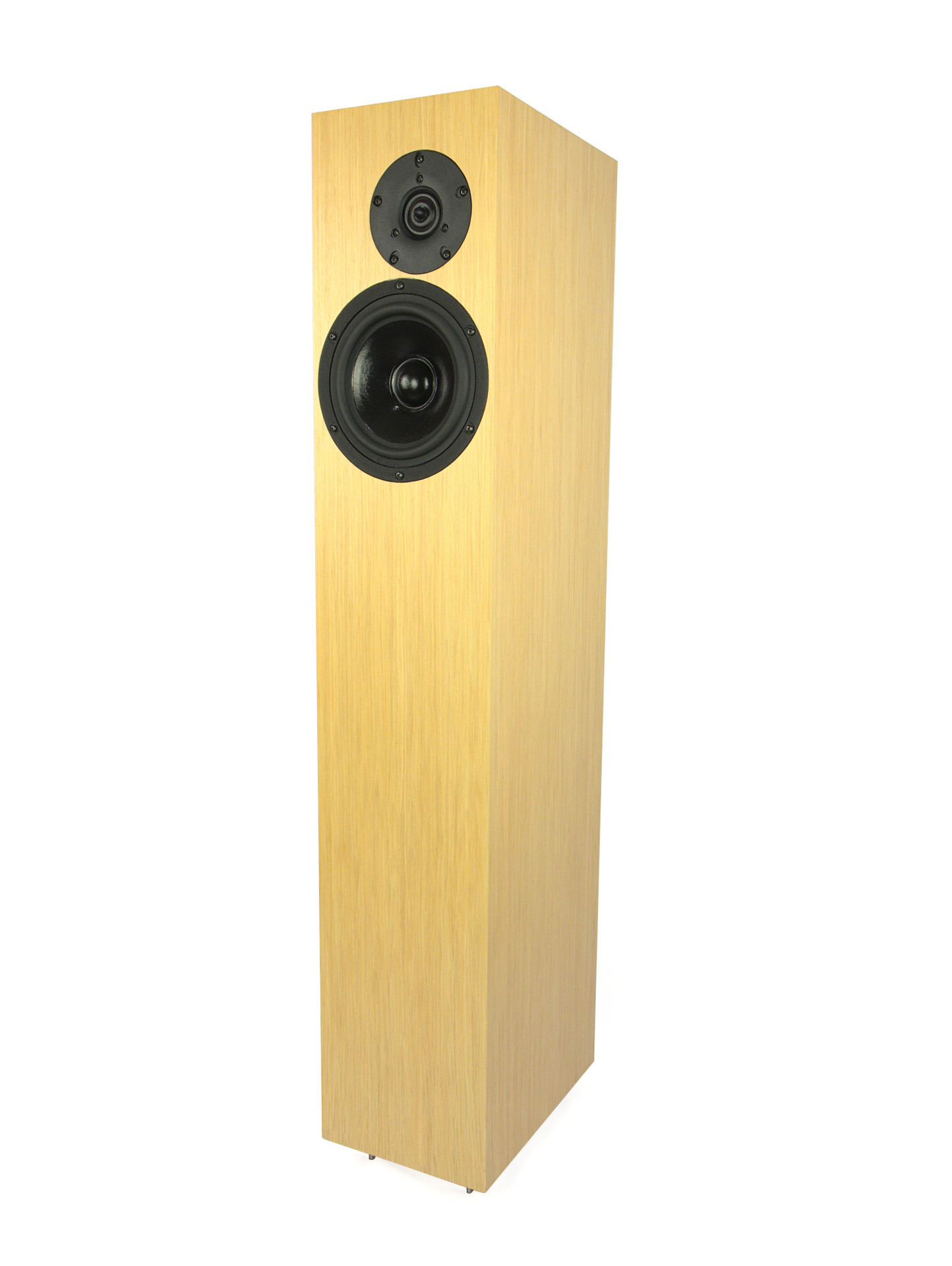
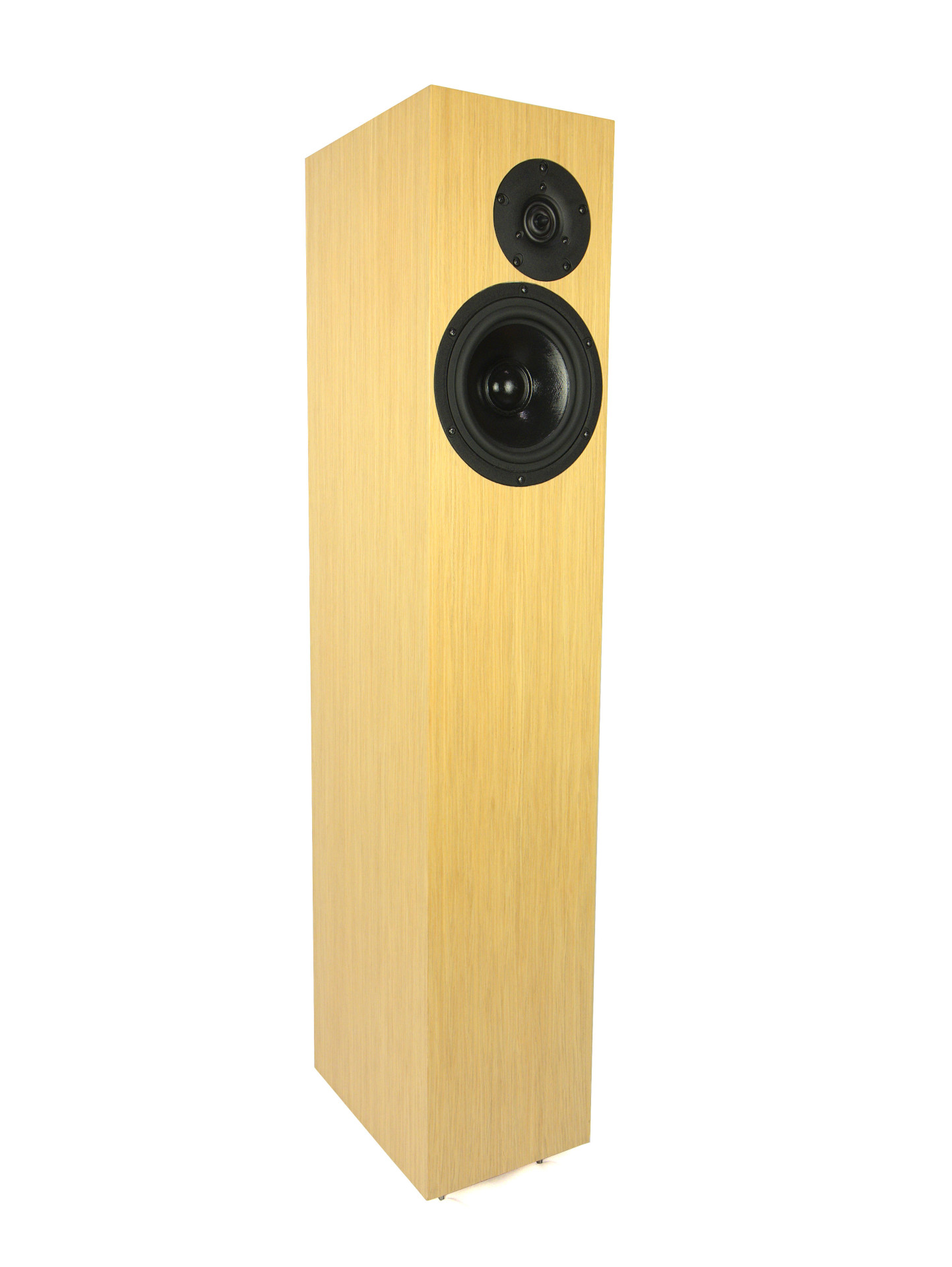
They came out beautiful. Given that this was my first time – I was more then satisfied.
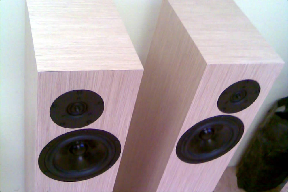
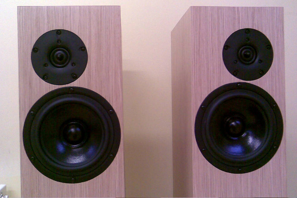
Sorry for photo quality. No DSLR for me back then. I promise I will make it up by the end of this article…
And so they went to my living room. First impressions were very pleasant and positive. I will not lie – I was really afraid I screwed something up. Back then 600€ was a lot of money for me. Hell, it’s not something to throw around even today. But after some listening I was filled with joy and happiness. I felt I did a right thing here. And so they were my pride and joy for some time to come.
Fast forward to somewhere around 2010 and I bought my first measuring mic. I had acquired some other drivers over the years and wanted to finally make something of my own. But first I decided to measure what I have created here.

dBSPL @1Meter on Tweeter axis, no smoothing, 3ms gate window.
Yeah… I always thought they had a lot of presence. No wonder. Now I see why. So it turns out I did screw something up after-all 🙂 And I listened to this screw-up for good two years… But the worst part is that it sounded really good! It goes to show once again how important it is to actually measure everything. Because relying on our highly biased and adaptive hearing is not good enough. Even to get the basic stuff right as SPL in this case.
What went wrong?
To my defense this speaker uses parallel cross-over. And this is not where you start your DIY speaker adventures. It’s really difficult to get it right even for the most experienced speaker designers. Hence why you don’t see many successful commercial designs using it. I won’t go in technical nit-picking about series vs. parallel crossovers. It was done many times before (e.g. read here). Bottom-line is they are theoretically equivalent, but when faced with a real driver having it’s non-linear impedance – there are some quirks.

Original cross-over schematics and resulting SPL by author. No measurement data provided.
As can be seen, original schematics are not very clear. Especially the 0.47mH-1.5Ω-10uF circuit part. Is it LCR circuit ? Or does the 0.47mH coil connects to a tweeter-woofer midpoint ? This is where I started to regret my “let’s quickly assemble filter together with a cabinet” approach… And why I thought it was input LCR back then ? Who knows. Ok, so I connected 0.47mH coil to a tweeter-woofer midpoint and made another measurement.

Corrected original cross-over schematics and resulting SPL@1Meter on Tweeter axis, no smoothing, 3ms gate window.
That’s better. But still, doesn’t look as smooth as original SPL graph. So I was lost. What’s going on here? And what that no-value resistor is doing near 10uF?

Updated cross-over schematics from authors web-site. Circa 2010.
It’s not there now! At this point I should probably have contacted the author and asked him this same question. But where is fun in doing so? And more importantly what I will learn then? Having both answers negative, I decided to figure it out myself.
Let’s simulate something…
So I thought then, how the hell I’m going to do that exactly? Well, it’s 2010 for god sake… Of course I will simulate it! Industry standard at that time (again, at least in DIY circles) was LspCAD by Swed named Ingemar Johansson. There was a demo version available. It was fully functional version 6.3 bundled with classical 5.25, except that project save function was disabled. I downloaded it and started to play with it.

I really liked it and after some time, when the DEMO version limitations were starting to get boring – I bought a standard version. Pricing was very sane then – 160€ for a software with that much functionality was a really good deal. I didn’t needed all additional optimization and advanced mechanical simulation included in pro version. I see that std version is discontinued now, you must pay 1k€ for a full pro one. That’s sad.

Check of a proper driver alignment in software. Measured combined drivers SPL (Grey reference) is compared to simulated (Blue).
From the beginning I liked 5.25 version better. It has more standard “one window” user interface and is more intuitive. At least for me personally. Even today I mostly use this classics. But there are things that it can’t do. Connecting components from different series networks is one of them. So I was forced to learn version 6.3 also. It’s not that hard when you get a hang of it. As with any software, finding the right drivers alignment (and especially dZ) is the key to a successful simulation results.
The truth is somewhere out there
Now let’s see how this “originally messed-up by me” cross-over should perform. Also let’s find out how it should be really connected.

Simulated “wrong” cross-over. Reference (grey) measured response.
Well, that’s obviously wrong. XT25TG shouldn’t be allowed to run down to 2kHz. And that huge 2-5kHz lift is (almost) exactly as measured. This gave me confidence that simulation results are agreeing to measured reality pretty well. Now let’s see what it should be like.

Simulated “right” cross-over. Reference (grey) measured response.
Again, resemblance with measured response is staggering. But we still have some problems. Tweeter level is too high (even for my liking) and there is some cancellation going on near a crossover region. Let’s fix this while we’re at it.

Simulated “new” cross-over. Reference (grey) measured response.
Couple small changes to R2, C2 and R3, C3 and we have much smoother SPL response. Tweeter is still on the hot side, but I so got used to more sparkle from these speakers, that I decided to leave it like that. After all, tweeter attenuation is more about preferences and listening environment then ruler flat SPL.
New cross-over phase tracking at 1 and 3 meters distance.
Phase tracking is much better now. And at my usual 3 meters listening position – it’s ideal.
The revelation
After final adjustments I had a good listening session and at first I was quite anxious. There was this feeling of something missing. And that’s understandable. Listening to music for couple of years with some +3dB at presence region has its effects on your expectations. But after few songs I realized how much well balanced overall picture was. Vocals were not in your face anymore but somewhere at the same distance with instruments. Cymbals sounded much more like cymbals and had no previous harshness. It was a huge change. And positive one.

Final measurement. dBSPL@1Meter on Tweeter axis, no smoothing, 3ms gate window. Right speaker (red), left speaker (blue).
When making final SPL measurements I noticed a small bump on left speaker @7kHz. I investigated it further and it turned out to be tweeter response.

Tweeter impedance and dBSPL@1Meter, no smoothing, 3ms gate window.
One was ruler flat and other had this small deviation. I didn’t investigate it further. Was it a production defect? Might be so. There was a small impedance wiggle at the same frequency, so this is something mechanical in nature. Sonically it doesn’t presented any problems so I leave it be.

Tweeter impedance and dBSPL@1Meter, no smoothing, 3ms gate window.
From a step response we can see that this heavily impregnated mid-woofer cone is not able to catch a tweeter. So it lags behind a little bit. That’s a price to pay for a smoother SPL and roll-off. Impedance is very sane 4.9Ω minimum.